4 nor flash control and status register, Table 8-10, Table 8-11 – Artesyn CPCI-6200 Installation and Use (May 2015) User Manual
Page 194: Nor flash control/status register, 0xf200_0003, Table 8-12, Nor flash control/status register field definition, Nor flash control and status register
Memory Maps and Addresses
CPCI-6200 Installation and Use (6806800J66E)
194
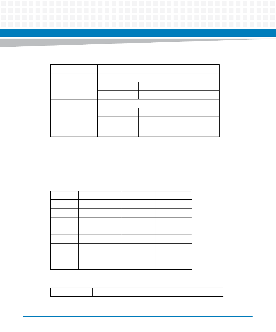
8.4.4
NOR Flash Control and Status Register
This register provides software-controlled bank write protect and map select functions as well
as boot block select, bank write protect, and activity status for the NOR flash.
Table 8-10 Front Panel LED Control/Status Register Field Definition
RSVD
Reserved
USR1_LED
User Green LED
1
Turn on the green LED.
0
Turn off green LED.
USR2_LED
User / Failure Indicating Yellow LED
1
Turn on the yellow LED
0
Turn off yellow LED. The board can also
turn on the LED if a failure condition is
detected.
Table 8-11 NOR Flash Control/Status Register, 0xF200_0003
Bit
Field
Operation
Reset
7
RSVD
R
0
6
RSVD
R
0
5
RSVD
R
0
4
MAP_SEL
R/W
0
3
F_WP_SW
R/W
1
2
F_WP_HW
R
X
1
FBT_BLK_SEL
R
X
0
FLASH_RDY
R
1
Table 8-12 NOR Flash Control/Status Register Field Definition
RSVD
Reserved