5 interrupt register 1, Table 8-13, Interrupt register 1, 0xf200_0004 – Artesyn CPCI-6200 Installation and Use (May 2015) User Manual
Page 196: Table 8-14, Interrupt register 1 field definition
Advertising
Memory Maps and Addresses
CPCI-6200 Installation and Use (6806800J66E)
196
8.4.5
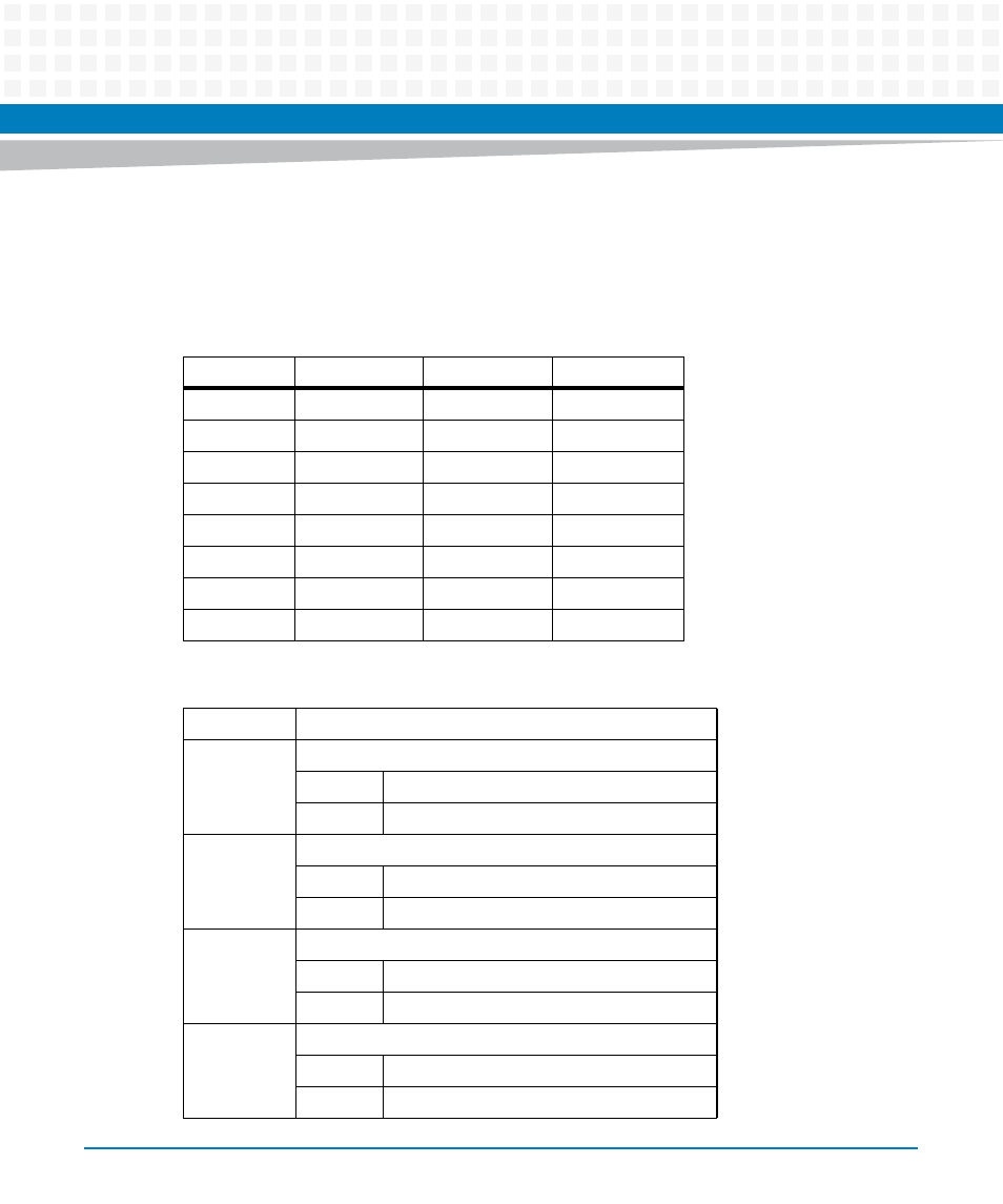
Interrupt Register 1
This register may be read by the system software to determine which of the Ethernet PHYs
originated their combined (OR'd) interrupt.
Table 8-13 Interrupt Register 1, 0xF200_0004
Bit
Field
Operation
Reset
7
RSVD
R
0
6
RSVD
R
0
5
RSVD
R
0
4
RSVD
R
0
3
PHY 4
R
0
2
PHY 3
R
0
1
PHY 2
R
0
0
PHY 1
R
0
Table 8-14 Interrupt Register 1 Field Definition
RSVD
Reserved
PHY 4
TSEC4 Interrupt
1
TSEC4 interrupt is asserted.
0
TSEC4 interrupt is not asserted.
PHY 3
TSEC3 Interrupt
1
TSEC3 interrupt is asserted.
TSEC3 interrupt is not asserted.
PHY 2
TSEC2 Interrupt
1
TSEC2 interrupt is asserted.
0
TSEC2 interrupt is not asserted.
PHY 1
TSEC1 Interrupt
1
TSEC1 interrupt is asserted.
0
TSEC1 interrupt is not asserted.
Advertising