Transition module preparation and installation – Artesyn CPCI-6200 Installation and Use (May 2015) User Manual
Page 119
Transition Module Preparation and Installation
CPCI-6200 Installation and Use (6806800J66E)
119
13
PMC2IO5
PMC2IO4
PMC2IO3
PMC2IO2
PMC2IO1
13
12
PMC2IO10
PMC2IO9
PMC2IO8
PMC2IO7
PMC2IO6
12
11
PMC2IO15
PMC2IO14
PMC2IO13
PMC2IO12
PMC2IO11
11
10
PMC2IO20
PMC2IO19
PMC2IO18
PMC2IO17
PMC2IO16
10
9
PMC2IO25
PMC2IO24
PMC2IO23
PMC2IO22
PMC2IO21
9
8
PMC2IO30
PMC2IO29
PMC2IO28
PMC2IO27
PMC2IO26
8
7
PMC2IO35
PMC2IO34
PMC2IO33
PMC2IO32
PMC2IO31
7
6
PMC2IO40
PMC2IO39
PMC2IO38
PMC2IO37
PMC2IO36
6
5
PMC2IO45
PMC2IO44
PMC2IO43
PMC2IO42
PMC2IO41
5
4
PMC2IO50
PMC2IO49
PMC2IO48
PMC2IO47
PMC2IO46
4
3
PMC2IO55
PMC2IO54
PMC2IO53
PMC2IO52
PMC2IO51
3
2
PMC2IO60
PMC2IO59
PMC2IO58
PMC2IO57
PMC2IO56
2
1
TMPRSNT_L
PMC2IO64
PMC2IO63
PMC2IO62
PMC2IO61
1
Signal Descriptions
PMCIO:
PMC2IO(1:64)
PMC 2 I/O signals 1 through 64
EIDE Primary Port (ATA-2):
DIORA_L -
I/O read
DIOWA_L -
I/O write
DIORDYA -
indicates drive ready for I/O
DD(15:0) -
IDE data lines
CS1FXA_L -
chip select drive 0 or command register block select
CS3FXA_L -
chip select drive 1 or command register block select
DA(2:0) -
drive register and data port address lines
DRESET_L -
drive reset
Serial COM Ports 1-4:
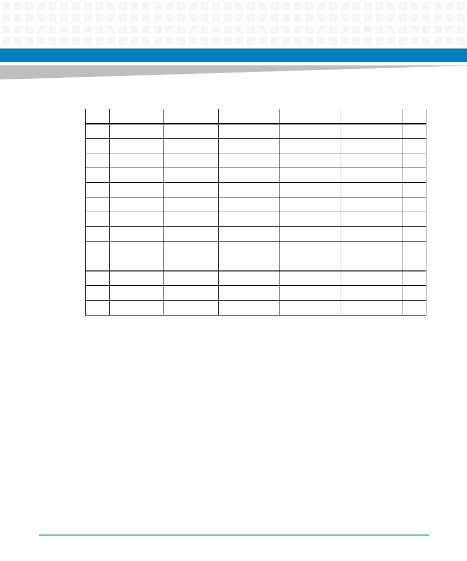
Table 5-8 User I/O Connector Pinout, J5 (continued)
Pin
Row A
Row B
Row C
Row D
Row E
Pin