3 cpci user i/o connector, j3, Table 3-4, Cpci user i/o connector pinout, j3 – Artesyn CPCI-6200 Installation and Use (May 2015) User Manual
Page 62: Controls, leds, and connectors
Controls, LEDs, and Connectors
CPCI-6200 Installation and Use (6806800J66E)
62
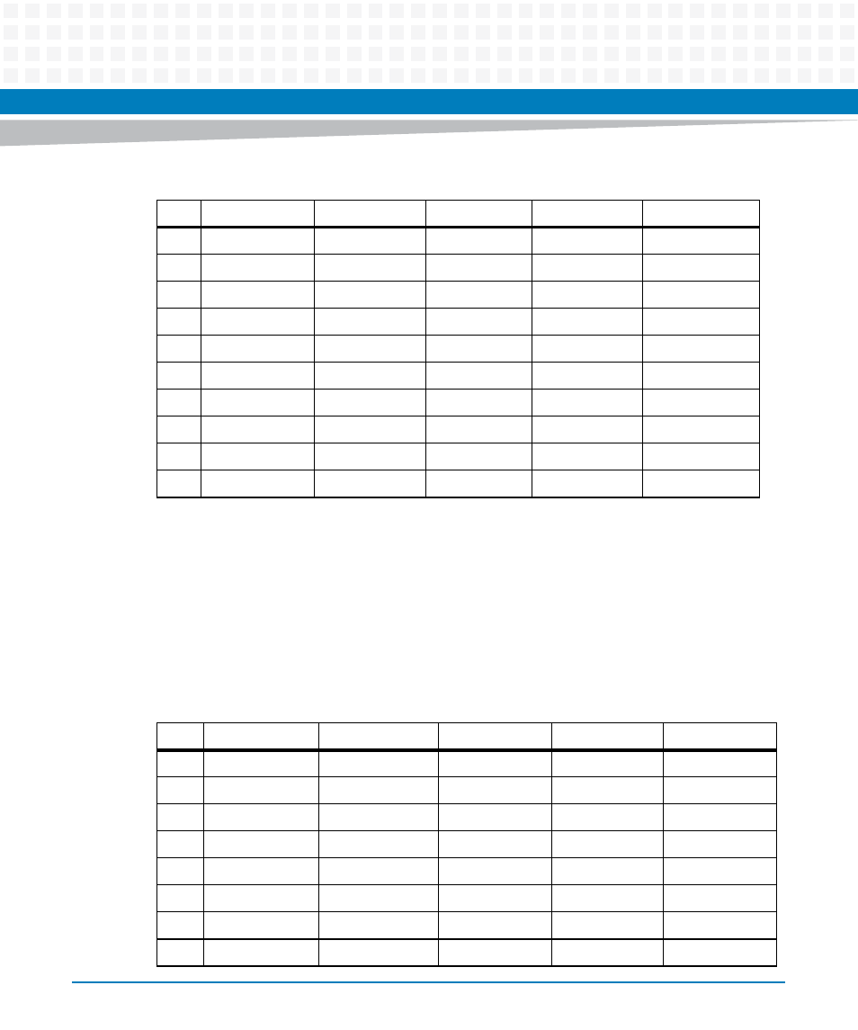
3.3.3
CPCI User I/O Connector, J3
J3 is a five-row user I/O CPCI connector.
Note: Row F is ground and is not shown in the table.
10
AD[49]
AD[48]
AD[47]
GND
AD[46]
9
AD[52]
GND
V(IO)
AD[51]
AD[50]
8
AD[56]
AD[55]
AD[54]
GND
AD[53]
7
AD[59]
GND
V(IO)
AD[58]
AD[57]
6
AD[63]
AD[62]
AD[61]
GND
AD[60]
5
C/BE[5]#
64EN#
V(IO)
C/BE[4]#
PAR64
4
V(IO)
BRSVP2B4
C/BE[7]#
GND
C/BE[6]#
3
RSV
GND
RSV
RSV
RSV
2
RSV
RSV
SYSEN#
1
RSV
RSV
1
RSV
GND
RSV
RSV
RSV
1. Defined as SYSEN#. This OV allows the CPCI-6200 to ensure that it is installed into a peripheral slot.
Table 3-3 CPCI Bus Connector Pinout, J2 (continued)
Pin
Row A
Row B
Row C
Row D
Row E
Table 3-4 CPCI User I/O Connector Pinout, J3
Pin
Row A
Row B
Row C
Row D
Row E
1
IPMI_PWR
PMCIO64
PMCIO63
PMCIO62
PMCIO61
2
PMCIO60
PMCIO59
PMCIO58
PMCIO57
PMCIO56
3
PMCIO55
PMCIO54
PMCIO53
PMCIO52
PMCIO51
4
PMCIO50
PMCIO49
PMCIO48
PMCIO47
PMCIO46
5
PMCIO45
PMCIO44
PMCIO43
PMCIO42
PMCIO41
6
PMCIO40
PMCIO39
PMCIO38
PMCIO37
PMCIO36
7
PMCIO35
PMCIO34
PMCIO33
PMCIO32
PMCIO31
8
PMCIO30
PMCIO29
PMCIO28
PMCIO27
PMCIO26