15 boundary scan header, p5, 16 processor cop header, p6, Table 3-15 – Artesyn CPCI-6200 Installation and Use (May 2015) User Manual
Page 77: Boundary scan header pinout, p5, Table 3-16, Cop header pinout, p6, Controls, leds, and connectors
Controls, LEDs, and Connectors
CPCI-6200 Installation and Use (6806800J66E)
77
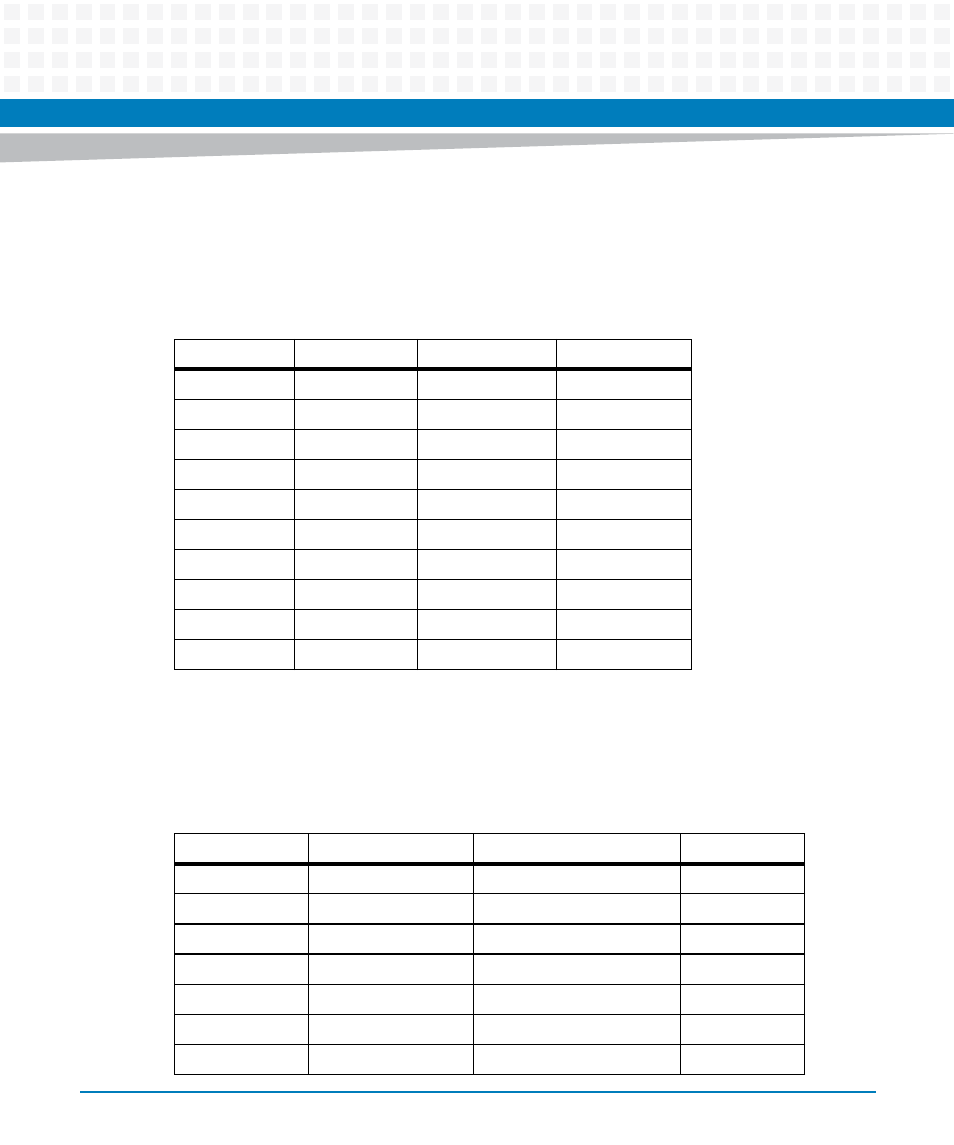
3.3.15 Boundary Scan Header, P5
The CPCI-6200 uses a standard 20-pin boundary scan port header that provides an interface for
programming the onboard PLDs, and boundary scan testing and debugging.
3.3.16 Processor COP Header, P6
The CPCI-6200 uses one standard 16-pin header to provide access to the COP function.
Table 3-15 Boundary Scan Header Pinout, P5
Pin Number
Signal
Signal
Pin Number
1
TCK
GND
2
3
TDO
GND
4
5
TMS
GND
6
7
TRST#
GND
8
9
TDI
BSCAN_EN#
10
11
Key (no pin)
NC
12
13
GND
BSCAN_AW#
14
15
GND
NC
16
17
GND
NC
18
19
GND
NC
20
Table 3-16 COP Header Pinout, P6
Pin Number
Signal
Signal
Pin Number
1
CPU_TDO
Not Connected
2
3
CPU_TDI
CPU_TRST#
4
5
Pull up
CPU_VIO pull-up
6
7
CPU_TCK
CPU_CKSTPI#
8
9
CPU_TMS
Not Connected
10
11
CPU_SRST#
GND (optional pull-down)
12
13
CPU_HRST#
Key (no pin)
14