6 jumper settings, Table 5-11, Wire interconnection list rj-45 to db-9 – Artesyn CPCI-6200 Installation and Use (May 2015) User Manual
Page 122: Transition module preparation and installation
Transition Module Preparation and Installation
CPCI-6200 Installation and Use (6806800J66E)
122
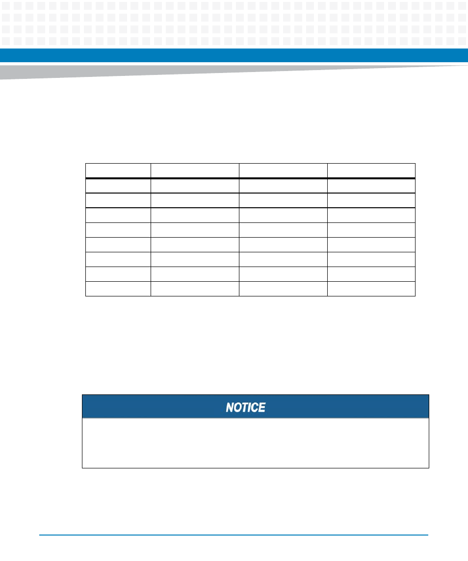
Connecting an CPCI-6200 to a PC terminal requires that the adapter described above be
attached to a standard RJ-45-to-RJ-45 shielded cable with straight through signaling.
The pinout information for this adapter is in the following table:
5.6
Jumper Settings
This section describes the jumper settings that are required for proper operation prior to
installing the CPCI-6115-MCPTM transition module into a chassis backplane. Many boards are
already factory configured based on customer requirements, but the jumper settings should
be verified before installation.
Table 5-11 Wire Interconnection List RJ-45 to DB-9
RF-45 Signal
RJ-45 Pin
DB-9 Pin
DB-9 Signal
DCD
1
4
DTR
RTS
2
8
CTS
GND
3
5
GND
TxD
4
2
RxD
RxD
5
3
TxD
GND
6
OPEN
CTS
7
7
RTS
DTR
8
6
DSR
Damage of the Product
Setting/resetting the switches during operation can cause damage of the product.
Check and change switch settings before you install the product.