6 i2c device addresses, Figure 8-2, Pci interrupt mapping to processor – Artesyn CPCI-6200 Installation and Use (May 2015) User Manual
Page 222: C device addresses
Memory Maps and Addresses
CPCI-6200 Installation and Use (6806800J66E)
222
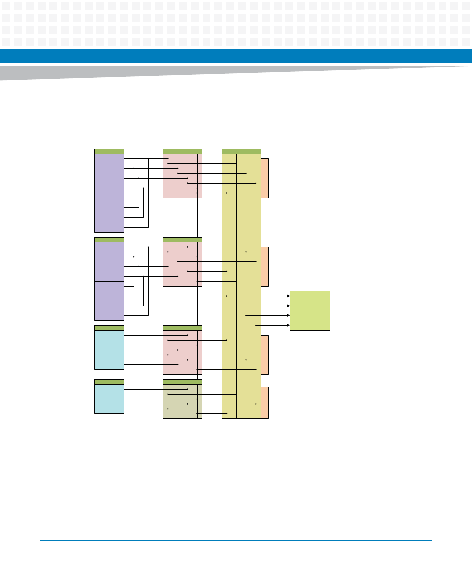
The following figure shows how PCI interrupts are mapped to processor interrupts.
8.6
I
2
C Device Addresses
A two-wire serial interface for the CPCI-6200 is provided by an I
2
C compatible serial controller
integrated into the MPC8572. The MPC8572 I
2
C controller is used by the system software to
read the contents of the various I
2
C devices located on the CPCI-6200.
Figure 8-2
PCI Interrupt Mapping to Processor
Primary
INTA_N
INTB_N
INTC_N
INTD_N
Secondary
INTA_N
INTB_N
INTC_N
INTD_N
Primary
INTA_N
INTB_N
INTC_N
INTD_N
Secondary
INTA_N
INTB_N
INTC_N
INTD_N
CPCI
INTA_N
INTB_N
INTC_N
INTD_N
INTA_N
INTB_N
INTC_N
8572
(Processor)
IN
T
A
_
N
IN
T
B
_
N
IN
T
C
_N
IN
T
D
_N
Tsi384 (PCI 1)
Tsi384 (PCI 2)
Tsi384 (PCI 3)
Tsi381 (PCI 4)
IN
T
A
_
N
IN
T
B
_
N
IN
T
C
_N
IN
T
D
_N
PEX8624
Po
rt
5
Po
rt
6
Po
rt
8
Po
rt
9
IRQ0_N
IRQ1_N
IRQ2_N
IRQ3_N
PMC1
PMC2
CPCI CPLD
USB CONT.
IN
T
A
_
N
IN
T
B
_
N
IN
T
C
_
N
IN
T
D
_
N