Virtual and hardware outputs, Bestlogic expression builder, Figure 7-5. bestlogic expression builder screen -7 – Basler Electric BE1-851 User Manual
Page 147
When the relay is powered up, all logic outputs are disabled and most variables (including virtual outputs)
initialize as FALSE. Some variable states are stored in EEPROM and are restored to the last state before
loss of power. These variables include 43/143/243/343, 101SC and SG0 through SG3. All control
commands, including logic override control, are also stored in EEPROM. If you override output logic and
force output to open, that condition will be maintained even if operating power is cycled.
Logic equations are defined by logic variables, logic operators, and their position in an equation. The
available logic operators include AND (*), OR (+), and NOT (/). The NOT operator is applied to the
variable immediately following the symbol (/). For virtual output equations, OR logic can be applied to any
number of variables if no AND logic is used in the expression. Similarly, AND logic can be applied to any
number of variables if no OR logic is used. Any number of NOT operators may be used. For complex
expressions that use both AND and OR operators, OR logic is limited to four terms. Up to four AND terms
with any number of variables can be Ored together. When the relay is processing a complex expression,
it performs AND operations before performing OR operations.
Virtual and Hardware Outputs
A virtual output exists only as a logical state inside the relay. A hardware output is a physical relay contact
that can be used for protection or control. Each BE1-851 relay has five isolated, normally open (NO)
output contacts (OUT1-OUT5) and one isolated, normally closed (NC) or normally open (NO) alarm
output (OUTA). Output contacts OUT1 through OUT5 are controlled by the status of the internal virtual
logic signals VO1 through VO5. If VO[n] becomes TRUE, then the corresponding output relay OUT[n]
energizes and closes the NO contacts. For the alarm output, if VOA becomes TRUE, the ALM output de-
energizes and closes. More information about input and output functions is provided in Section 3, Input
and Output Functions.
Hardware outputs can also be controlled by the CO-OUT (control operate, output) ASCII command. The
CO-OUT command overrides control of logic outputs. Outputs may be pulsed or latched in a 0 or 1 state
independently from the state of the virtual output logic. More information about overriding control of logic
outputs is available in Section 3, Input and Output Functions.
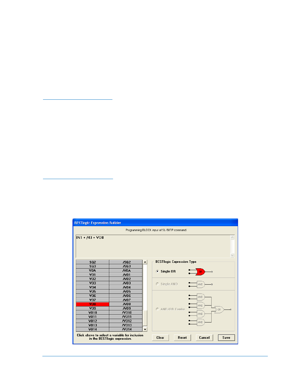
BESTlogic Expression Builder
The BESTlogic Expression Builder is used to connect the inputs of the relay’s function blocks, physical
inputs and outputs, and virtual outputs. Using the BESTlogic Expression Builder is analogous to
physically attaching wire between discrete relay terminals. The BESTlogic Expression Builder is opened
each time the input of a BESTlogic function block is selected. Figure 7-5 illustrates the BESTlogic
Expression Builder Screen.
Figure 7-5. BESTlogic Expression Builder Screen
9289900990 Rev R
BE1-851 BESTlogic™ Programmable Logic
7-7