Equation 4-1. time oc characteristics for trip -16 – Basler Electric BE1-851 User Manual
Page 72
The pickup value determines the level of current required for the element to start timing toward a trip.
Time Dial is used to select the time delay between pickup and trip based on the selected Curve. See
Appendix A, Time Overcurrent Characteristic Curves.
The unit of measure for the Pickup setting defaults to secondary amps though it is selectable for primary
amps (Pri Amps), per unit amps (Per U Amps), and percent amps (% Amps).
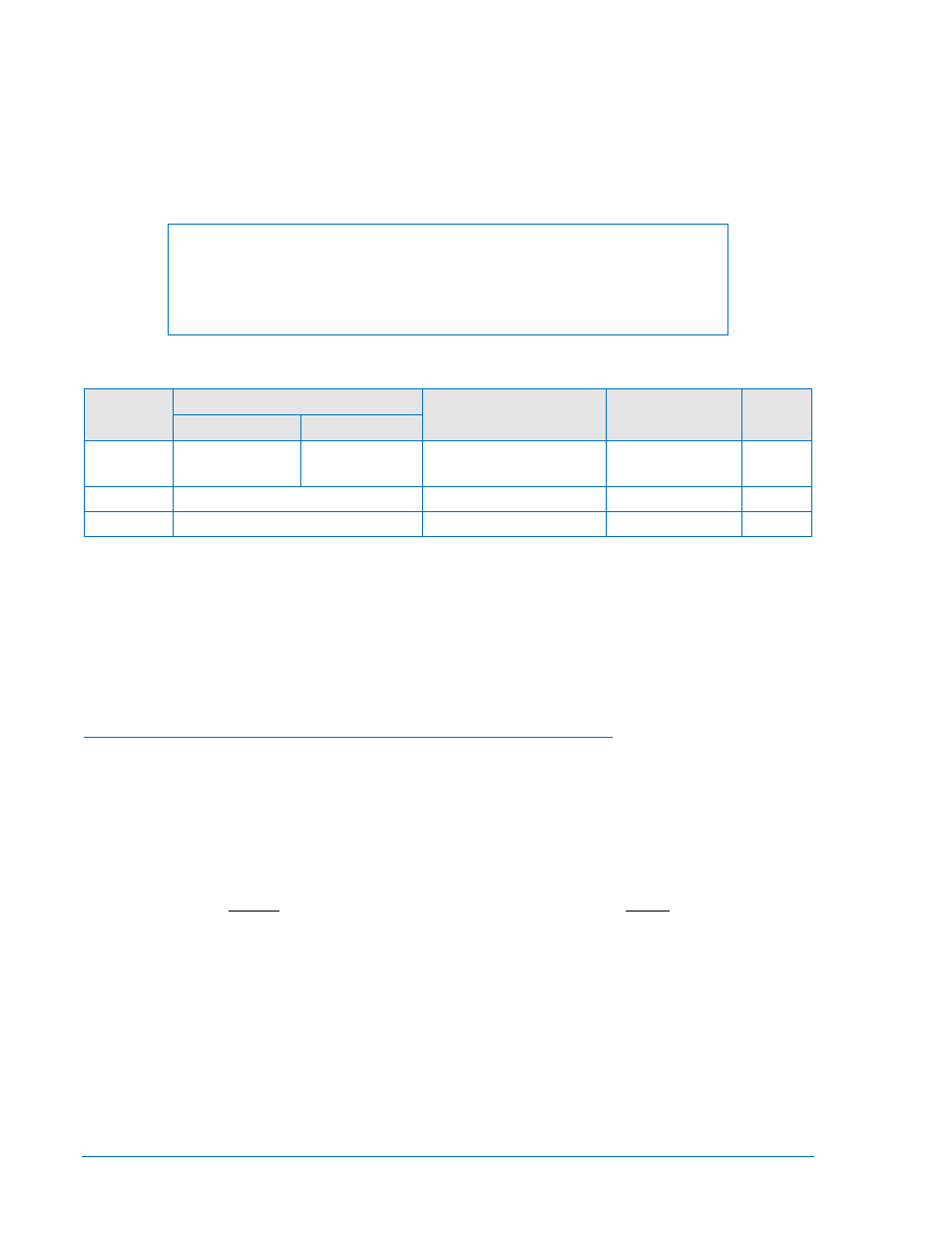
Using the pull-down menus and buttons, make the application appropriate settings to the time overcurrent
element. Table 4-7 summarizes the operating settings for Time Overcurrent Protection.
NOTE
Changing settings while the relay is in service will return an error message (PU
CONDITON) if the new setting is within approximately 90 percent of the
metered current level. This is intended to prevent the user from inadvertently
causing a trip when changing a setting.
Table 4-7. Operating Settings for Time Overcurrent Protection
Setting
Range
Increment
Unit of Measure Default
1 A
5 A
Pickup
0 = Disabled
0.1 to 3.2
0 = Disabled
0.5 to 16
0.01 for 0.1 to 9.99
0.1 for 10.0 to 16.0
Secondary Amps
0
Time Dial
0.0 to 9.9
0.1
N/A
0
Curve
See Appendix A, Table A-1
N/A
N/A
V2
Example 1. Make the following operating settings to the 51P element. Refer to Figure 4-15.
Logic:
User
Settings:
Setting Group 0
Pickup:
10 secondary amps
Time Dial:
2.4
Curve:
S1R
Setting Programmable Time Current Characteristic Curve Coefficients
Equation 4-1 and Equation 4-2 define time current characteristics for trip and reset respectively. These
equations comply with IEEE standard C37.112-1996. The curve specific coefficients are defined for the
standard curves as listed in Appendix A, Time Overcurrent Characteristic Curves. Standard curves can be
selected for each 51 or 151 protection element by selecting them from the desired elements Curve pull-
down menu. When time current characteristic curve P is selected, the coefficients used in the equation
are those defined by the user. Definitions for these equations are provided in Table 4-8.
K
BD
C
M
AD
T
N
T
+
+
−
=
Equation 4-1. Time OC Characteristics for Trip
1
2
−
=
M
RD
T
R
Equation 4-2. Time OC Characteristics for Reset
4-16
BE1-851 Protection and Control
9289900990 Rev R