Overcurrent protection, Overcurrent protection -10 – Basler Electric BE1-851 User Manual
Page 66
Overcurrent Protection
BE1-851 overcurrent protection includes instantaneous elements for Phase, Neutral, and Negative-
Sequence, as well as time overcurrent elements for Phase, Neutral, and Negative-Sequence.
50T - Instantaneous Overcurrent Protection with Settable Time Delay
There are two independent BESTlogic function blocks for phase (50TP, 150TP), two for neutral (50TN,
150TN), and two for negative-sequence (50TQ, 150TQ) instantaneous overcurrent protection. Sensing
input type G relays have four neutral elements and two phase elements. Sensing input type H units have
two neutral, two phase, and two negative-sequence elements. The BESTlogic mode setting can connect
each function block to any of the CT inputs. The instantaneous overcurrent functions are labeled 50T and
150T because each function has an adjustable time delay. If a function block has a time delay setting of
zero, then that function block will operate as an instantaneous overcurrent relay.
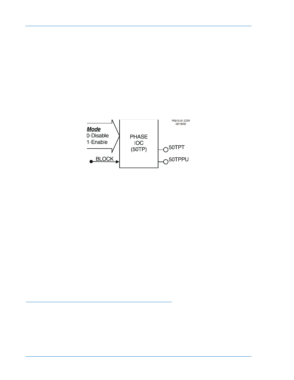
Each of the six independent function blocks has two logic outputs, pickup, and trip. A T at the end of its
label indicates the trip output and a PU indicates pickup. The first letter of the label indicates the element
type where P is a phase element, N is a neutral element, and Q is a negative-sequence element. The 50T
element illustrated in Figure 4-9 is a phase element.
Figure 4-9. Instantaneous Overcurrent Logic Block
Each function block has a Block input that can be used to disable the function. A BESTlogic expression is
used to define the Block input. When this expression is TRUE, forcing the outputs to logic zero and
resetting the timers to zero disable the function block. This feature functions in a similar way to the torque
control contact of an electro-mechanical relay.
A logic mode input allows each instantaneous overcurrent function block to be enabled or disabled. More
information about logic mode selection is provided in the following paragraph titled BESTlogic Settings for
Instantaneous Overcurrent paragraph.
Each instantaneous overcurrent function has a pickup and time delay setting. When the measured current
increases above the pickup threshold, the pickup output (x50TPPU) becomes TRUE and the timer starts.
If the current stays above pickup for the duration of the time delay setting, the trip output (x50TPT)
becomes TRUE. If the current decreases below the dropout ratio, which is 95 percent of pickup, the timer
is reset to zero (¼ to ½ cycles later).
The phase overcurrent protective functions include three independent comparators and timers, one for
each phase. If the current increases above the pickup setting for any one phase, the pickup output
asserts. If the trip condition is TRUE for any one phase, the trip logic output asserts.
If the target is enabled for the function block, the target reporting function will record a target for the
appropriate phase when the protective function trip output is TRUE and the fault recording function trip
logic expression is TRUE. See Section 6, Reporting and Alarms, Fault Reporting, for more information
about target reporting.
BESTlogic™ Settings for Instantaneous Overcurrent Protection
BESTlogic settings are made from the BESTlogic Function Element screen in BESTCOMS. Figure 4-10
illustrates the BESTCOMS screen used to select BESTlogic settings for the Instantaneous Overcurrent
element. To open the BESTlogic Function Element screen for Instantaneous Overcurrent with Settable
Time Delay, select Overcurrent from the Screens pull-down menu and select either the 50T or 150T tab.
Then select the BESTlogic button for the element you wish to edit. Alternately, logic settings for the 50T
and 150T functions can be made using the SL-x50T ASCII command.
4-10
BE1-851 Protection and Control
9289900990 Rev R