Logic timers, 62 - general purpose logic timers, Logic timers -23 – Basler Electric BE1-851 User Manual
Page 79: 62 - general purpose logic timers -23
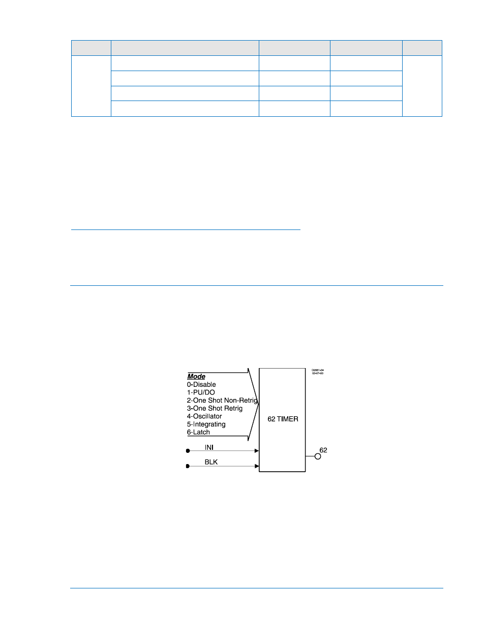
Table 4-12. Operating Settings for Breaker Failure Protection
Setting
Range
Increment
Unit of Measure Default
Time
0 = Disabled
N/A
N/A
0
50 to 999 ms
1 ms
Milliseconds
0.05 to 0.999 sec.
0.001 sec.
Seconds
0 to 59.96 (60 Hz) or 0 to 49.97 (50 Hz)
∗
Cycles
∗
Time delays less than 10 cycles can be entered to the nearest 0.1 cycles from the HMI. All time delays
can be entered to the nearest 0.01 cycles from the ASCII command interface. Time delays entered in
cycles are converted to milliseconds or seconds. Increment precision after conversion is limited to that
appropriate for each of those units of measure.
Example 1.
Make the following operating settings to the Breaker Failure element. See Figure 4-20.
Logic:
User
Timer Setting, Time: 10.02 cycles
Retrieving Breaker Failure Protection Status from the Relay
The status of each logic variable can be determined from the ASCII command interface using the RG-
STAT (report general-status) command. Logic status cannot be determined using BESTCOMS. See
Section 6, Reporting and Alarms, General Status Reporting, for more information.
Logic Timers
62 - General Purpose Logic Timers
BE1-851 relays provide two general-purpose logic timers that are extremely versatile. Two additional
general-purpose logic timers are available when style option 1 is V or W. Each can be set for one of five
modes of operation to emulate virtually any type of timer. Each function block has one output (x62, where
x = none, 1, 2, or 3) that is asserted when the timing criteria has been met according to the BESTlogic
mode setting. Figure 4-21 shows the 62 function block as an example. Each mode of operation is
described in detail in the following paragraphs.
Figure 4-21. General Purpose Logic Timers Logic Block
An INITIATE logic input is provided to start the timing sequence.
A BLOCK logic input is provided to block operation of the timer. When this expression is TRUE, the
function is disabled.
Each timer has a T1 time setting and a T2 time setting. The functioning of these settings is dependent
upon the type of timer as specified by the mode setting in BESTlogic.
If the target is enabled for the function block, the target reporting function will record a target when the
timer output is TRUE and the fault recording function trip logic expression is TRUE. See Section 6,
Reporting and Alarms, Fault Reporting, for more details on the target reporting function.
9289900990 Rev R
BE1-851 Protection and Control
4-23