Gnss antenna connector, Table 22: acceptable cable lengths, The gnss antenna connector provides – NavCom SF-3050 Rev.B User Manual
Page 108
SF-3050 User Guide – Rev B
GNSS Antenna Connector
The connector used on the SF-3050 is a TNC female,
labeled ANT on the rear panel of the sensor as
shown in Figure 40.
The GNSS antenna connector
provides
+5V
± 0.5V at 100mA
. Do not
disconnect the antenna when the
GNSS unit is powered on.
The system is supplied with 12ft (3.6m) of RG58/U
cable (P/N 94-310261-3012LF). The cable is fitted
with two straight male TNC connectors.
The cable length between the antenna and SF-3050
should not exceed 7dB loss at 1.575GHz for optimum
performance, though the system may tolerate up to
10dB of cable loss with minimal performance. Lower
elevation satellite tracking suffers the most with more
than 7dB insertion loss.
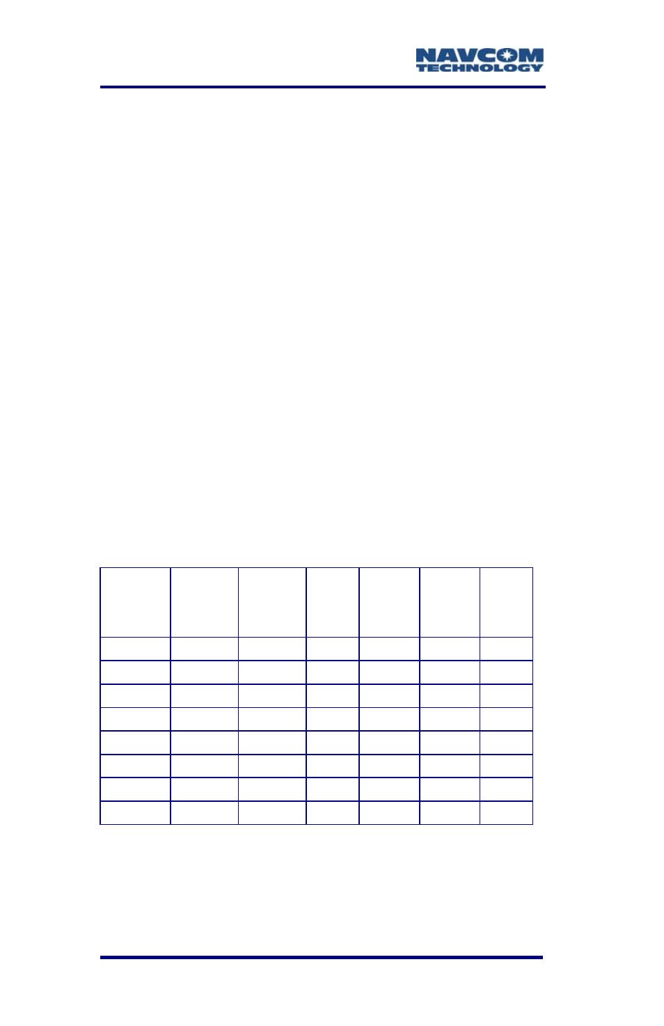
Table 22: Acceptable Cable Lengths
Cable
Type
Atten.
(dB) per
100 Ft.
Cable
Length
in Feet
Loss
in dB
Atten.
(dB)
per
100 m
Cable
Length
in
Meters
Loss
in dB
RG-58C 19.605 36.00 7.06 64.32 11.00 7.08
RG-142 16.494 43.00 7.09 54.12 13.00 7.04
RG-213
9.564 74.00 7.08 31.38 22.50 7.06
RG-223 17.224 41.00 7.06 56.51 12.50 7.06
LMR600 3.407 207.00 7.05 11.18 63.00 7.04
LMR400 5.262 133.00 7.00 17.26 41.00 7.08
LMR240 10.127 70.00 7.09 33.23 21.00 6.98
LMR195 14.902 47.00 7.00 48.89 14.00 6.85
In-line amplifiers suitable for all GNSS frequencies
may be used to increase the length of the antenna
cable, but care should be exercised that tracking
performance is not degraded due to multiple
4-106