D event input configuration, Event input configuration, Figure 81: event cable wiring diagram – NavCom SF-3050 Rev.B User Manual
Page 157: Table 27: event wiring connections, D ...................... event input configuration
SF-3050 User Guide – Rev B
D ...................... Event Input Configuration
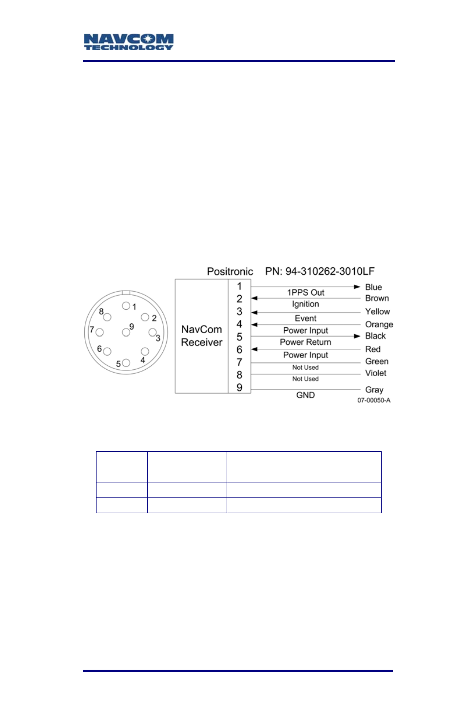
Figure 81 details the wiring of the supplied Event
cable assembly. NavCom part number P/N 94-
310262-3010LF is supplied with earlier SF-3050
production units. P/N 94-310274-3010LF is supplied
with later SF-3050 production units.
Refer to Chapter 3/Event for detailed electrical
specifications.
Table 27 details the wiring configuration required for
Event pulse sensing.
Figure 81: Event Cable Wiring Diagram
Table 27: Event Wiring Connections
Pin #
Signal
Name
Event Sync Wiring
3
Event
Tie Event to Ground
9 Ground
N/A
Once the cable is wired to correspond with the event
pulse requirements, configure the receiver to output
the message containing a time mark, referenced to
the time kept within the receiver, indicating when the
event is sensed (EVENTLATCH, EVENTLATCHA).
Messages EVENTLATCH and
EVENTLATCHA are described in the
D-155