Parameter tables, 1 vcb-x bacnet parameters, Pt-link ii bacnet3 interface 32 – Orion System PT-Link II BACnet3 User Manual
Page 32: Zone
Zone
Zone
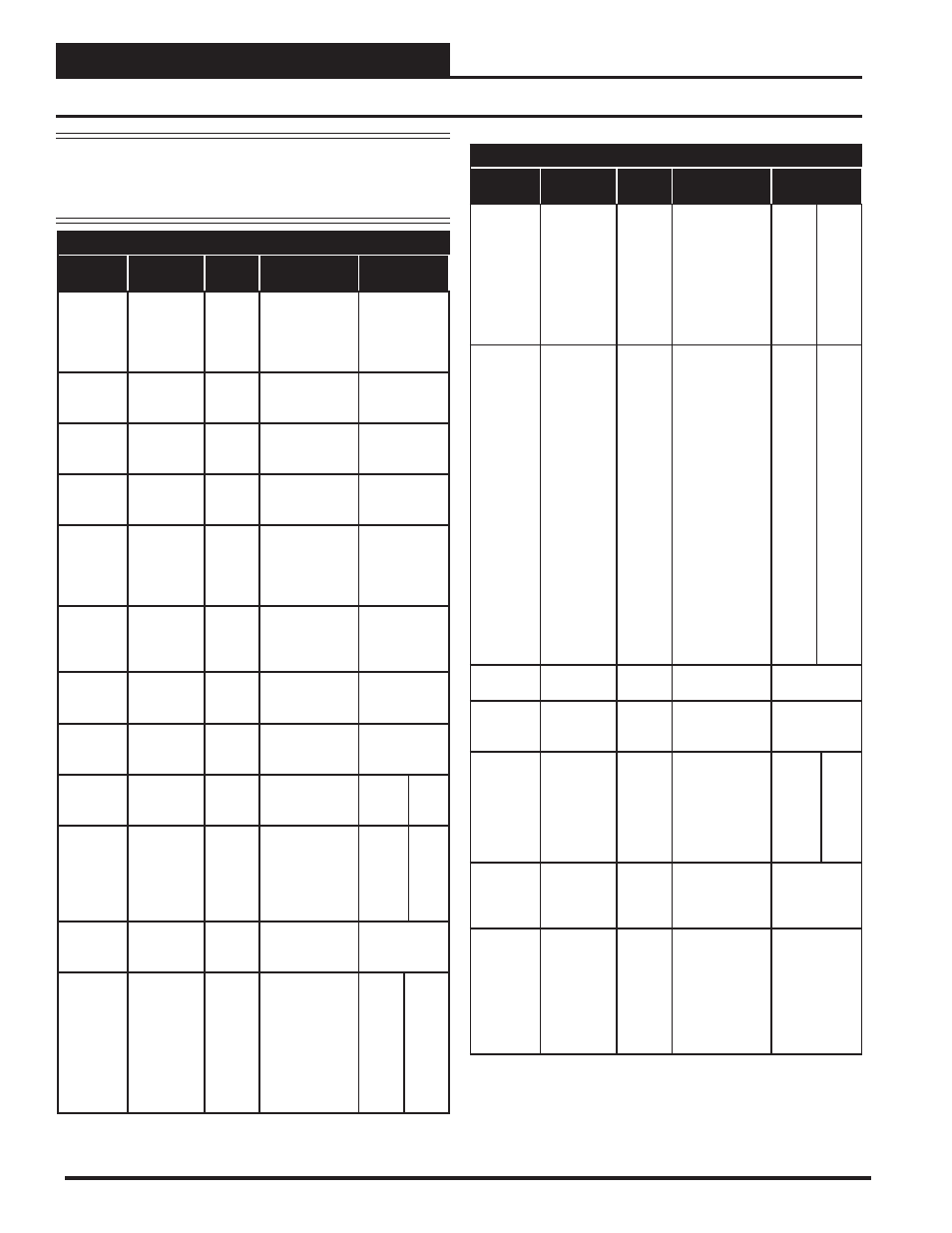
7. PARAMETER TABLES
PT-Link II BACnet3 Interface
32
7.1 VCB-X BACnet Parameters
BACnet Properties for the VCB-X Controller
Param-
eter
Name
Object
Description
Limits
Bad or
Missing 12
Relay
Expansion
Board.
Mis12Rly
BI: 376
The 12 Relay
Expansion Board
is confi gured but
not detected.
Alarm
Group 1
AlmGrp1
AI: 104
See Alarm
Group Bits on
page 43.
Alarm
Group 2
AlmGrp2
AI: 105
See Alarm
Group Bits on
page 43.
Alarm
Group 3
AlmGrp3
AI: 106
See Alarm
Group Bits on
page 43.
Alarm
Status
AlmSts
AI: 1
Indicates that
there is an alarm.
0 = Off
1 = On
See Alarm
Group Bits on
page 43.
Appli-
cation
Software
Version
AppVer
AI: 99
Current version
of the software
in the unit.
Unit Mode
UnitMode
AI:123
See Unit Mode
Bits on page
43.
Building
Pressure
BuildPr
AI:272
Current value of
the Building
Pressure Sensor.
Building
Pressure
Setpoint
RfPrSt
AV:118
Current Building
Pressure
Setpoint.
-.20
.20
Building
Pressure
Control
Deadband
RfPrDb
AV:358
Value above
and below the
Building Pres-
sure Setpoint
where no control
change occurs.
.01
0.1
CO
2
CO2
AI:271
Current CO
2
Level.
CO
2
Sensor
Calibration
Deadband
Offset
CO2Ost
AV: 348
If the CO
2
Sensor is reading
incorrectly, you
can use this
option to enter
an offset value
to adjust the
Sensor’s CO
2
reading.
-500
ppm
500
ppm
BACnet Properties for the VCB-X Controller
Param-
eter
Name
Object
Description
Limits
CO
2
Minimum
Setpoint
CO2MinLv
AV:287
This is the
threshold CO
2
level at which
the Economizer
Min Damper
Position
Setpoint will
begin to be reset
higher.
0
2000
CO
2
Maximum
Setpoint
CO2
MaxLv
AV:288
This is the CO
2
level at which
the Economizer
Min Damper
Position will
be reset to the
Economizer Max
Position in High
CO
2
. In between
the Min and
Max CO
2
levels
the Economizer
Min Damper
Position will be
proportionally
reset between the
confi gured Min
Damper Position
and the Max
Position in High
CO
2
.
0
2000
Bad CO
2
Sensor
CO2Alm
BI: 368
Failure of the
CO
2
Sensor.
Coil
Tempera-
ture
CoilTp
AI: 181
Current coil
temperature
reading.
Coil
Tempera-
ture Offset
ColTpOft
AV:284
If the Coil
Temperature
Sensor is reading
incorrectly, use
this offset to ad-
just the Sensor’s
Temperature.
-100
100
Bad Coil
Pressure
Sensor
ColPrAlm
BI: 367
Failure of the
Coil Pressure
Sensor. Will shut
unit down.
Coil Tem-
perature
Setpoint
CoilTpSt
AI: 334
This is the
current
calculated Coil
Suction
Temperature
target during
Dehumidifi cation
Mode.
NOTE:
When using Celsius scaling, all temperature values will
need to be divided by 10 by the BMS to properly read
the status and setpoint values, e.g., a value of 200º C
needs to be divided by 10 for an actual value of 20º C.