Quick pt-link set-up, 1 quick start guide, Pt-link ii bacnet3 interface – Orion System PT-Link II BACnet3 User Manual
Page 5: Figure 1: pt-link ii bacnet, Dimensions and components
PT-Link II BACnet3 Interface
2. QUICK PT-LINK SET-UP
5
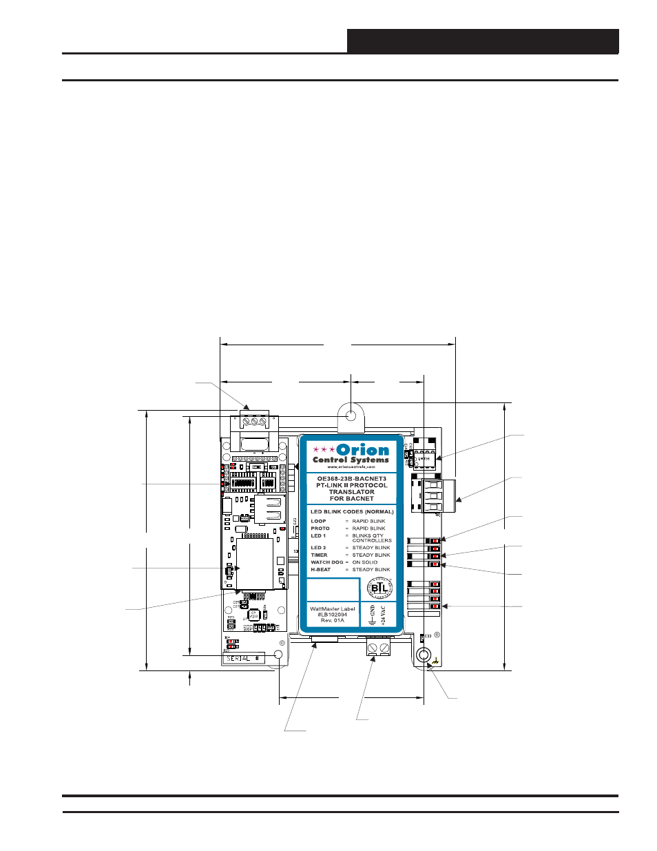
2.1 Quick Start Guide
Figure 1: PT-Link II BACnet
®
Dimensions and Components
485
DRIVER
COMM
R
SH
T
LOOP
PROTO
LED1
LED2
TIMER
W_DOG
H-BEAT
POWER
MADE IN USA
4.82
4.70
0.27
4.31
1.31
2.61
4.25
2.37
0.20 Dia.
Mounting Hole
Typ. 3 PL.
BACnet
®
Communications
Wiring Terminal
Local Loop
Communications
Wiring Terminal
Local Loop
Communications
Driver Chip
24 VAC Power
Terminal
Communications
LED
Diagnostic
LED #1
Diagnostic
LED #2
BACnet
®
Protocessor
Module
Power
LED
USB
Port
Ethernet
Port
Configuration
DIP Switches
IAEZH004
Made in USA
1
2
3
4
5
6
7
8
O
N
O
N
1
2
3
4
ON
RSGND
The following steps will get you up and running in no time:
1.
Familiarize yourself with the PT-Link II components (Figure 1).
2.
Connect your PT-Link II to the Controller(s) on your system (up
to four) and connect your PT-Link II to the BACnet Network
(Figure 2).
NOTE:
Controllers must be addressed as
1, 2, 3 & 4.
3.
Obtain the following from your Building Automation System
Integrator: the BACnet MAC address (System Node ID) and the
MS/TP network baud rate. Also, relay to your System Integrator
that the BACnet Device Instance Number for the PT-Link will be
the MAC address + 50,000. If this Device Instance will not work,
then continue to the full setup.
4. Confi gure your PT Link DIP Switches. See Section 2.3, page 7.
• Set the BACnet MS/TP baud rate via the B Bank set of DIP
switches.
•
Set the BACnet MS/TP MAC Address using the PT-Link A
Bank DIP switches. The BACnet MS/TP MAC Address
MUST be set between 1 and 127.