Parameter tables, 5 vcm-x bacnet parameters, Pt-link ii bacnet3 interface – Orion System PT-Link II BACnet3 User Manual
Page 49
PT-Link II BACnet3 Interface
7. PARAMETER TABLES
49
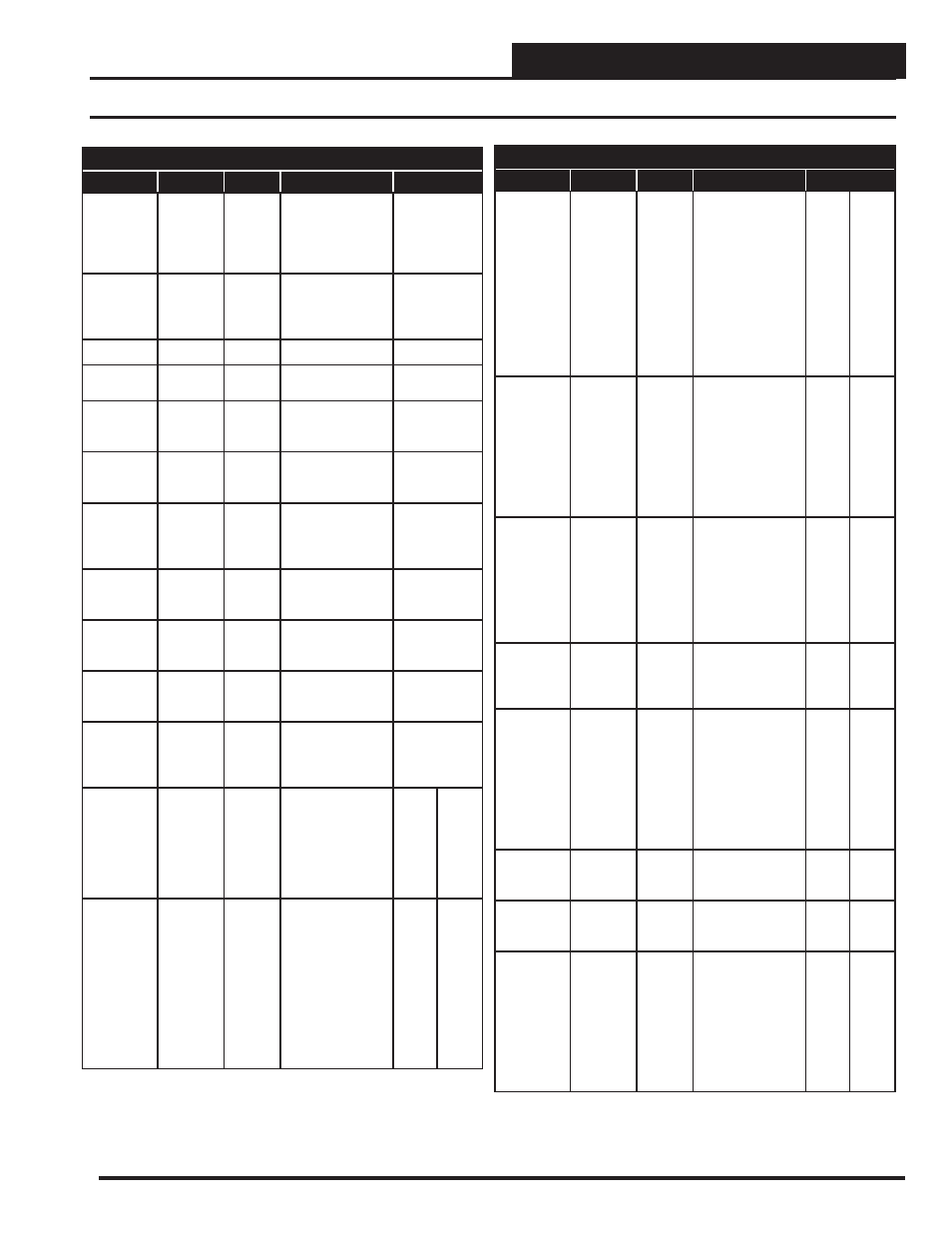
7.5 VCM-X BACnet Parameters
BACnet Properties for the VCM-X Controller
Parameter
Name
Object
Description
Limits
Modulating
Cool
Position
MdClPos
AI: 115
Current position of
the modulating
cooling signal
(Chilled water or
digital compressor).
Modulating
Heat
Position
MdHtPos
AI: 116
Current position of
the modulating
heating signal (hot
water or SCR heat).
Unit Mode
UnitMode
AI: 123
See page 53.
Return Air
CO
2
Level
CO2Level
AI: 150
Current value of the
CO
2
sensor.
Bypass
Damper
Position
ByPas-
Dmp
AI: 153
Current position of
the bypass damper
signal.
Return
Damper
Position
RaDmp
AI: 154
Current position of
the return damper
signal.
Coil
Temperature
CoilTp
AI: 181
Current coil
temperature reading
added on version
1.09.
Outdoor Air
CFM
OaCFM
AI: 193
Current Outdoor
Airfl ow
Measurement
Exhaust
CFM
EtCFM
AI: 194
Current Exhaust
Airfl ow
Measurement
Supply Air
CFM
SaCFM
AI: 195
Current Supply
Airfl ow
Measurement
Current
Calculated
OA CFM
setpoint
OACfm-
StM
AI: 205
Current calculated
Outdoor Air CFM
based on CO
2
level.
Dewpoint
Setpoint
DptSt
AV: 13
If the outdoor
dewpoint rises
above this setpoint,
the unit will
activate the
Dehumidifi cation
Demand.
35
80
Occupied/
Mode
Enable
Cooling
Setpoint
OcpClSt
AV: 42
If the control tem-
perature rises one
degree above this
setpoint, the control
will activate the
cooling demand. If
the control tempera-
ture is the Supply
Air Sensor, then the
cooling demand is
always active.
0
99
BACnet Properties for the VCM-X Controller
Parameter
Name
Object
Description
Limits
Occupied/
Mode
Enable
Heating
Setpoint
OcpHtSt
AV: 43
If the control
temperature drops
one degree below
this setpoint,
the control will
activate the heating
demand. If the
control
temperature
is the Supply Air
Sensor, then there is
no heating demand.
0
99
Outdoor
Air Sensor
Offset
OaTpOst
AV: 53
If the Outdoor
Temperature Sensor
is reading
incorrectly, you can
use this option to
enter an offset
temperature to
adjust the Sensor’s
Temperature.
-100
100
Return
Air Sensor
Offset
RaTpOst
AV: 65
If the Return Tem-
perature Sensor is
reading incorrectly,
you can use this
option to enter an
offset temperature
to adjust the Sen-
sor’s Temperature.
-100
100
Schedule
Force
SchdFrc
AV: 66
0 = Auto/
Unoccupied Mode
1 = Forced On
2 = Forced Off
0
2
Space
Sensor
Offset
SpcTpOst
AV: 71
If the Space
Temperature
Sensor is reading
incorrectly, you can
use this option to
enter an offset
temperature to
adjust the Sensor’s
Temperature.
-100
100
SAT
Cooling
Setpoint
SaClSt
AV: 77
Supply Air Setpoint
in Cooling Mode.
40
80
SAT
Heating
Setpoint
SaHtSt
AV: 78
Supply Air Setpoint
in Heating Mode.
40
200
Supply
Air Sensor
Offset
SaTpOst
AV: 80
If the Supply Air
Temperature Sensor
is reading incor-
rectly, you can use
this option to enter
an offset
temperature to
adjust the Sensor’s
Temperature.
-100
100