Verilink ConnecT 56K DSU (896-502110-001) Product Manual User Manual
Page 43
2 = TEST
ConnecT 56K DS
User Manual
3-13
Operation
Follow standard operating procedure. When 2=TEST is flashing: Press
the Enter button resulting in the displaying of the first two submenu
items.
1=Local Unit
2=Remote Unit
Use the number 1 key to activate the 1=Local Unit Test submenu press the
Enter key to enter the submenu resulting in the displaying of two
submenu choices.
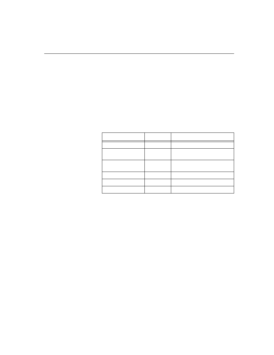
Table 3-3
Test Commands
1 = DTE & LOOP (LL)
The DTE and LOOP test splits the ConnecT 56K DSU into separate DTE
and loop interface sections and then loops the receive data of each
interface back to its respective transmit data. A block diagram illustrating
the loopback points and the signal paths for this test is shown in
Table A-1, “DTE and Loop Test Diagram,” on page A -8.
When the LL lead from the DTE is activated, the test described above is
also performed by the ConnecT 56K DSU. The ConnecT 56K DSU
acknowledges this DTE activated test by activating the TM on the DTE
interface.
This particular test permits the separate sections of the ConnecT 56K
DSU to be checked. First, it allows the local DTE interface drivers and
receivers to be tested with an external data analyzer or data from the DTE
device. Second, it allows the loop interface section of the local DSU to be
tested from the remote site over the actual communications circuit.
Front Panel
AT Command
Description
1=DTE & LOOP (LL)
&T10
TD/RD and RX/TX Loopbacks
2=LOOP ONLY (RT)
&T11
RX/TX Loopback with DTE
interface
3=DTE ONLY
&T1
TX/RX Loopback at network
interface
4=DTE WITH TP
&T8
TX/RX Loopback with test pattern
5=TEST PATTERN
&T9
Transmit/receive test pattern
6=SELF TEST
NA
Check internal components