Application module – Verilink PRISM 3030 (34-00208.L) Product Manual User Manual
Page 19
Application Module Installation
9
ALM
RLY
GND NO C NC
SLOT 1
ETHERNET
NMS
IN
NMS
OUT
SUPV
STATION
CLOCK
T1
DTE
T1
NET
O
I
O
I
REPLACE WITH SAME TYPE/RATING
ON
GND
+ -
2A
250 V
OFF
A SLOT 2 B
A SLOT 3 B
DC Version
AC Version
FUSE 1.0A 250V SLO-BLOW
110/220 VAC
50-60HZ .4A/.2A
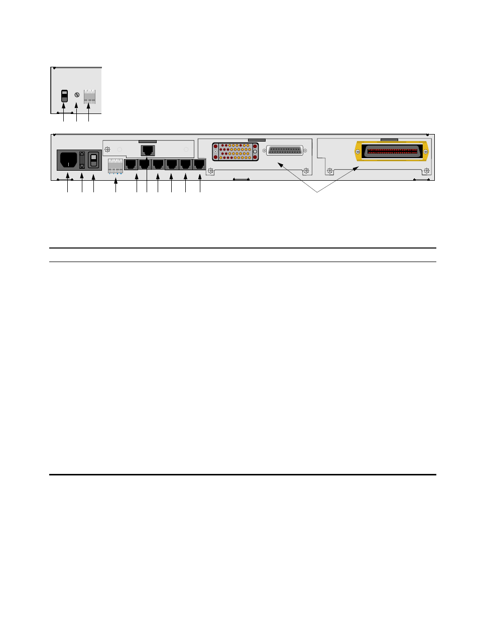
Figure 2-1 PRISM 3030 Rear Panel
1
2
3
4
5
6
8
9
10
7
11
12
13
14
Table 2-1 PRISM 3030 Rear Panel Connectors and Switches
Index
Item
Function
1
DC Power Switch
This switch turns the DC power ON or OFF.
2
DC Fuse
This DC fuse is rated at 2.0 amperes.
3
DC Connection
48 VDC power is connected to
+
and
–
. See DC Power Connection Procedure on page 19.
4
AC Connection
This 110/220 VAC power receptacle is rated at 50 –60 Hz, 0.6 A /0.3 A. See AC Power
Connection on page 18.
5
AC Fuse
This AC fuse is rated at 1.0 ampere and is shipped with a spare.
6
AC Power Switch
This switch controls the AC power (position
I
is ON and position
O
is OFF).
7
Alarm Relay
The Normally Closed alarm connects to NC & C. The Normally Open alarm connects to NO
& C.
8
NMS
This is the network management system input/output. Refer to NMS Connection on page 15.
9
SUPV
Supervisory port connection. Refer to Supervisory Port Connection on page 16.
10
Station Clock
The N×56/64 kHz or 1.544 MHz external station clock connector. Refer to
External Clock Connection on page 14.
11
T1 DTE
The T1 DTE port for drop and insert applications. Refer to 3010 Module Options on page 13.
12
T1 NET
The T1 network port. Refer to Network Connection on page 13.
13
Slot 1 - Ethernet
The Ethernet or Token Ring connection. Refer to LAN SNMP Connection on page 17.
14
Slots 2 and 3
Two
application module
s with up to two ports each may be inserted into each of these
slots. In this example, Slot 2 shows a combination V.35 and EIA-530
application module
.
Slot 3 shows an FXS voice
application module
.