3 operation, Introduction, Operation – Verilink PRISM 3030 (34-00208.L) Product Manual User Manual
Page 31: Peration
3
O
PERATION
Introduction
This chapter describes the screens and menus associated with the Verilink PRISM
3030 front panel LCD interface. The Terminal Operation chapter discusses the
screens and menus associated with the external terminal interface. In general, the
options are the same for both interfaces.
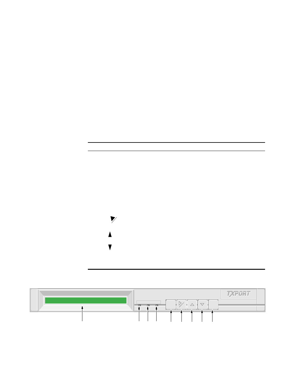
depicts the front panel which has three LED indicators, an LCD screen,
and five control buttons. Table 3-1 is referenced by number to the front panel
controls and indicators along with a brief description.
Table 3-1 Front Panel Controls and Indicators
Index
Control/Indicator
Function
1
LCD Display
This 2-line, 40-character wide window provides access to
unit configuration, diagnostics, and utilities.
2
ALARM (red)
This LED lights continuously when the unit is in an active
alarm condition.
3
TEST (yellow)
This LED lights continuously when line or DTE loops are set
or if the BERT function is operating.
4
POWER (green)
This LED lights continuously when power is applied to the
unit.
5
EXIT
Pressing this button returns the program to the previous
menu.
6
Pressing this button either moves the cursor one character to
the right or it clears the error counts. Pressing this button on
power up resets all parameters to the factory defaults.
7
Pressing this button scrolls the program up through the
elements /parameters.
8
Pressing this button scrolls the program down through the
elements /parameters.
9
SELECT
Pressing this button accesses a submenu or sets a parameter
to the displayed value.
CLR
ALARM
TEST
POWER
ALARM
TEST
POWER
EXIT
EXIT
SELECT
SELECT
CLR
CLR
Figure 3-1 3030 Front Panel
1
2
5
9
3
4
6
8
7