Data interface module (rear panel), 10/100 ethernet, Ethernet led indicators – Verilink WANsuite 7205 (34-00317.B) Product Manual User Manual
Page 24: Serial interfaces, Data interface module (rear panel) -10, 10/100 ethernet -10, Ethernet led indicators -10, Serial interfaces -10
1-10
W A N s u i t e 7 2 0 5
NOTICE:
For information on pinout assignments for this connector, refer to
page A-8. See Ordering Information on page A-6 for information on
cables for this connector.
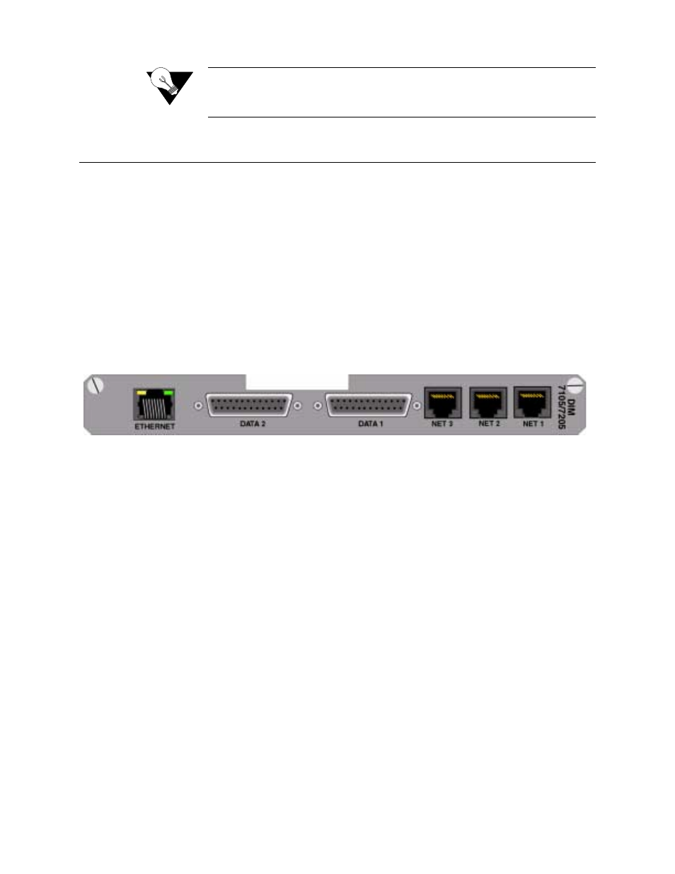
Data Interface Module (Rear Panel)
The Data Interface Module (DIM)
−
or rear connector module
−
mates with
the associated WANsuite 7205 module and connects it to the data equipment.
As shown in Figure 1.2, the rear panel of the DIM 7205 provides the
following:
•
Two RS-232 DB-25 connectors
•
Three RJ-48C jacks
•
One 8 -pin modular 10/100Base-T Ethernet port
The two DB-25 connectors are Serial data ports (labeled
DATA 1
and
DATA
2
), and the two RJ-48C jacks are Network interfaces (labeled
NET 3, NET 2,
and
NET 1
).
Figure 1.2
WANsuite 7205 Rear Panel
10/100 Ethernet
The WANsuite 7205 provides one
10/100 ETHERNET
interface for IP
Gateway, SNMP, and Web browser access. This interface is an 8-pin modular
jack that complies with standard twisted-pair, 10/100Base-T requirements.
The 10/100Base-T cable is supplied by the end user. Refer to Ethernet
Connection Pin Assignments on page A-9 for pin assignments and cable
descriptions.
Ethernet LED Indicators
There are two unlabeled indicator LEDs on either side of the 10/100 Ethernet
jack. The LED on the left side of the jack pulses amber to indicate data
activity (either transmit or receive). The LED on the right side of the jack
lights green to indicate that the link layer is operational.
Serial Interfaces
The two
SERIAL
interfaces (labeled
DATA 1
and
DATA 2
) located on the rear
of the unit are multi-protocol interfaces presented physically as DB-25
connections. The protocols supported by these interfaces are RS-232,
EIA-530, V.35, and X.21.