Network interfaces, Power connection, Network interfaces -11 – Verilink WANsuite 7205 (34-00317.B) Product Manual User Manual
Page 25: Power connection -11
A b o u t t h e W A N s u i t e 7 2 0 5
1-11
Cables that adapt the DB-25 interface to the 34-pin V.35 interface are
available. These cables are listed as optional equipment on page A-7 of
Appendix A. DB-25 to DB-25 cables also are available if your installation
needs require them. See Ordering Information on page A-6 for details. Refer
to Serial Interface Pin Assignments for DTE Mode (Packet Use Only) on
page A-8 and Serial Interface Pin Assignments for DCE Mode on page A-9
for Serial interface pin assignments.
CAUTION:
FCC rules require that interconnecting cables carrying high-speed
data be shielded appropriately in order to minimize radio frequency
interference.
Network Interfaces
Labeled on the rear panel of the WANsuite 7205 as
NET 1, NET 2, and NET 3
,
the Network interfaces’ connections are standard RJ-48C, 8-pin modular jacks
that contain an automatic line build out (ALBO). This ALBO allows the unit
to be located a substantial distance away from the telco Network interface
with a receive signal level to
−
27 dB. To view their pinout assignments, refer
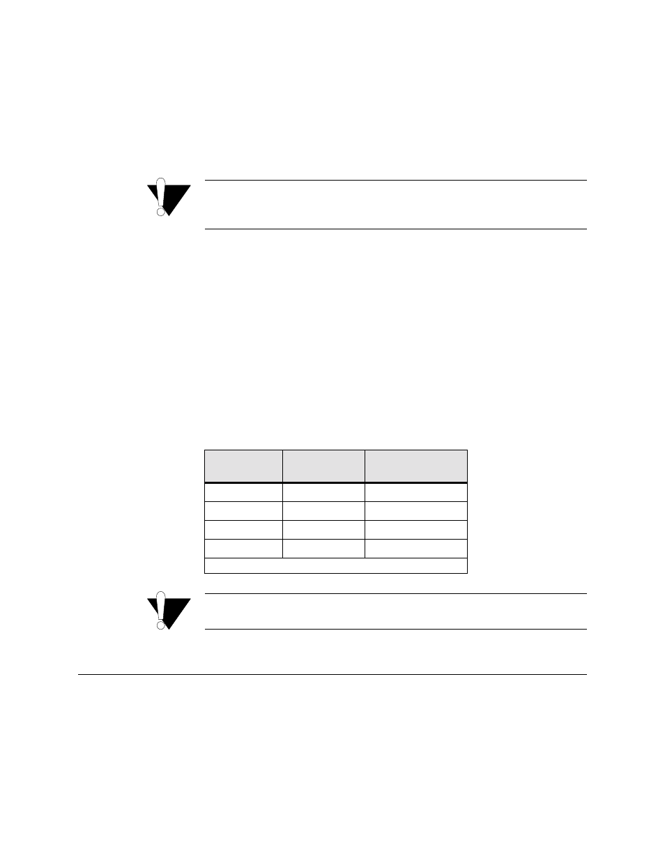
Maximum suggested cable lengths for the connection from the unit to the
network are listed in the table below. Calculations are based on a cable
temperature of 70
°
F, 0.083
µ
F /mile capacitance, a 27-dB loss, and a 100-
Ω
,
non-loaded, twisted-pair cable.
CAUTION:
In accordance with FCC Rules, Part 68.218(b), you must notify the
telephone company prior to disconnecting this product.
Power Connection
No external power supply is required for the WANsuite 7205; power is
received from its AS2000 rack connection.
When power is applied to the unit, the front panel LED indicators flash for
approximately 10 to15 seconds as the unit initializes. The green
POWER
LED
will remain illuminated as long as the unit receives power. This LED turns
amber when the unit is in test mode.
Cable Type
Loss per 1000 ft
(dB)
Max Cable Length
(ft)
26-gauge PIC
6.8
4,400
24-gauge PIC
5.4
5,500
22-gauge PIC
4.2
7,100
19-gauge PIC
3.0
10,000
(PIC - Plastic Insulated Cable)