Bidirectional mpls te tunnel configuration example, Network requirements, Configuration procedure – H3C Technologies H3C S6800 Series Switches User Manual
Page 115
102
Bidirectional MPLS TE tunnel configuration example
Network requirements
Switch A, Switch B, Switch C, and Switch D all run IS-IS and they are all level-2 switches.
Use RSVP-TE to establish a bidirectional MPLS TE tunnel between Switch A and Switch D.
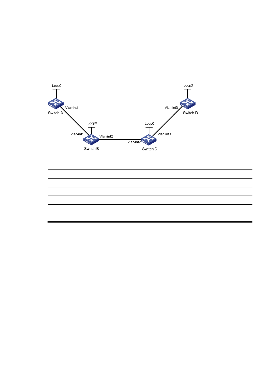
Figure 30 Network diagram
Table 5 Interface and IP address assignment
Device Interface IP
address
Device
Interface
IP address
Switch A
Loop0
1.1.1.9/32
Switch D
Loop0
4.4.4.9/32
Vlan-int1
10.1.1.1/24
Vlan-int3
30.1.1.2/24
Switch B
Loop0
2.2.2.9/32
Switch C
Loop0
3.3.3.9/32
Vlan-int1
10.1.1.2/24
Vlan-int3
30.1.1.1/24
Vlan-int2
20.1.1.1/24
Vlan-int2
20.1.1.2/24
Configuration procedure
1.
Configure IP addresses and masks for interfaces. (Details not shown.)
2.
Configure IS-IS to advertise interface addresses, including the loopback interface address.
For more information, see "
Establishing an MPLS TE tunnel with RSVP-TE
3.
Configure an LSR ID, and enable MPLS, MPLS TE, and RSVP-TE on each switch. Configure Switch
A and Switch D to assign a non-null label to the penultimate hop:
# Configure Switch A.
<SwitchA> system-view
[SwitchA] mpls lsr-id 1.1.1.9
[SwitchA] mpls label advertise non-null
[SwitchA] mpls te
[SwitchA-te] quit
[SwitchA] rsvp
[SwitchA-rsvp] quit
[SwitchA] interface vlan-interface 1
[SwitchA-Vlan-interface1] mpls enable
[SwitchA-Vlan-interface1] mpls te enable