Bidirectional mpls te tunnel – H3C Technologies H3C S6800 Series Switches User Manual
Page 74
61
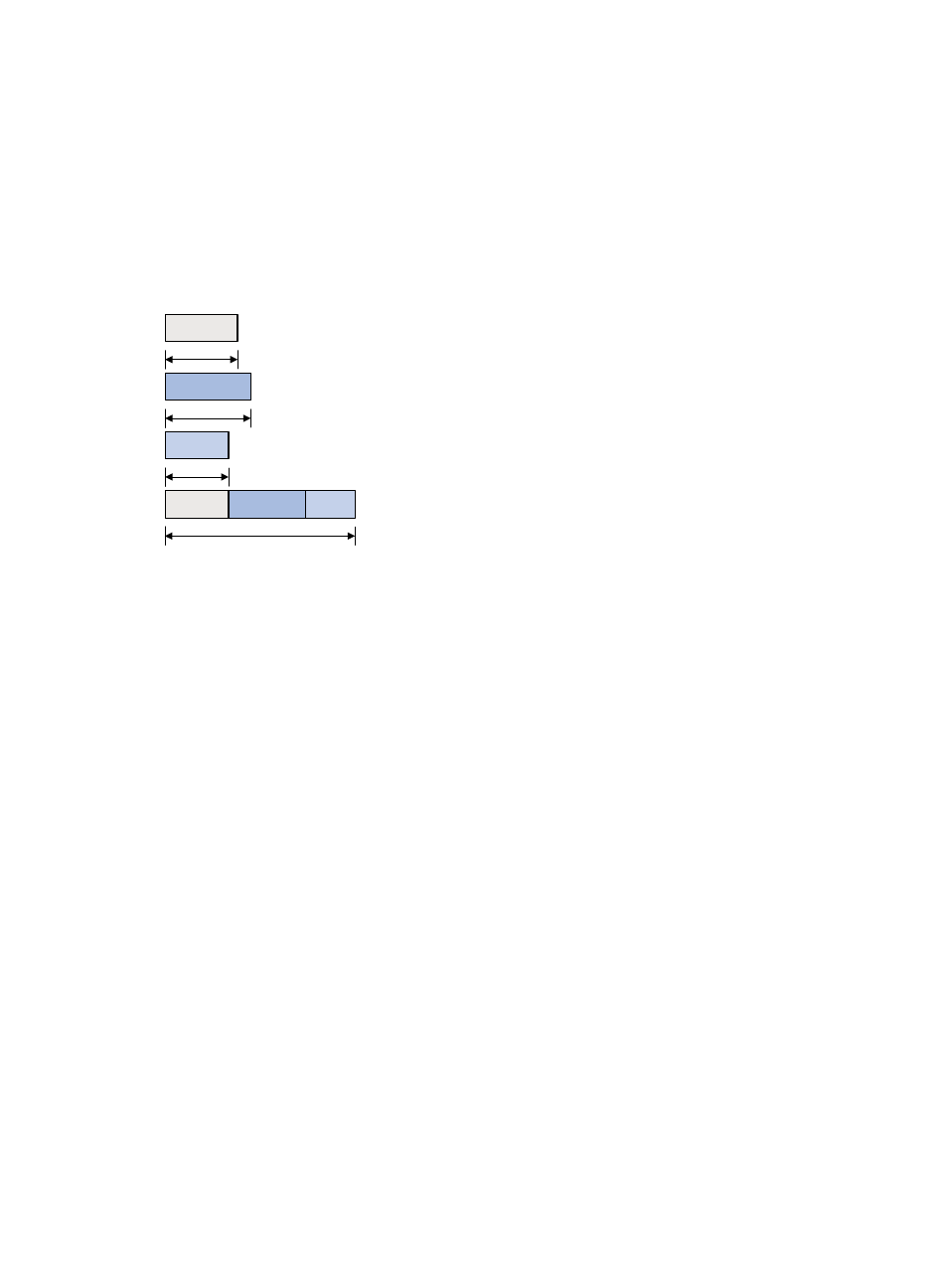
MAM is suitable for networks where traffic of each CT is stable and no traffic bursts occur.
shows an example:
•
BC 0 is for CT 0. The bandwidth occupied by the traffic of CT 0 cannot exceed BC 0.
•
BC 1 is for CT 1. The bandwidth occupied by the traffic of CT 1 cannot exceed BC 1.
•
BC 2 is for CT 2. The bandwidth occupied by the traffic of CT 2 cannot exceed BC 2.
•
The total bandwidth occupied by CT 0, CT 1, and CT 2 cannot exceed the maximum reservable
bandwidth.
Figure 26 MAM bandwidth constraints model
3.
Checks whether the CT and the LSP setup/holding priority match an existing TE class.
An MPLS TE tunnel can be established for the CT only when the following conditions are met:
{
Every node along the tunnel has a TE class that matches the CT and the LSP setup priority.
{
Every node along the tunnel has a TE class that matches the CT and the LSP holding priority.
Bidirectional MPLS TE tunnel
MPLS Transport Profile (MPLS-TP) uses bidirectional MPLS TE tunnels to implement 1:1 and 1+1 protection
switching and support in-band detection tools and signaling protocols such as OAM and PSC.
A bidirectional MPLS TE tunnel includes a pair of CRLSPs in opposite directions. It can be established in
the following modes:
•
Co-routed mode—Uses the extended RSVP-TE protocol to establish a bidirectional MPLS TE tunnel.
RSVP-TE uses a Path message to advertise the labels assigned by the upstream LSR to the
downstream LSR and a Resv message to advertise the labels assigned by the downstream LSR to the
upstream LSR. During the delivery of the path message, a CRLSP in one direction is established.
During the delivery of the Resv message, a CRLSP in the other direction is established. The CRLSPs
of a bidirectional MPLS TE tunnel established in co-routed mode use the same path.
•
Associated mode—In this mode, you establish a bidirectional MPLS TE tunnel by binding two
unidirectional CRLSPs in opposite directions. The two CRLSPs can be established in different modes
and use different paths. For example, one CRLSP is established statically and the other CRLSP is
established dynamically by RSVP-TE.
For more information about establishing MPLS TE tunnel through RSVP-TE, the Path message, and the Resv
message, see "
CT 2
CT 1
CT 0
BC 0
Max reservable BW
BC 1
BC 2
CT 0
CT 1
CT 2