Ietf ds-te configuration example, Network requirements, Configuration procedure – H3C Technologies H3C S6800 Series Switches User Manual
Page 137
124
IETF DS-TE configuration example
Network requirements
Switch A, Switch B, Switch C, and Switch D run IS-IS and all of them are Level-2 switches.
Use RSVP-TE to create a TE tunnel from Switch A to Switch D. Traffic of the tunnel belongs to CT 2, and
the tunnel needs a bandwidth of 4000 kbps.
The maximum bandwidth of the link that the tunnel traverses is 10000 kbps and the maximum reservable
bandwidth of the link is 10000 kbps. BC 1, BC 2, and BC 3 are 8000 kbps, 5000 kbps, and 2000 kbps.
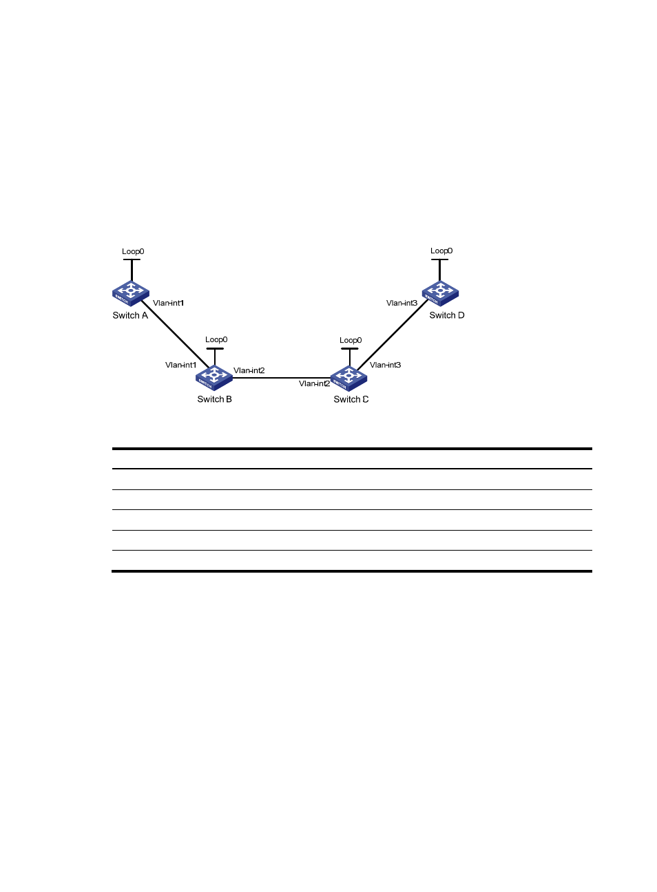
Figure 34 Network diagram
Table 9 Interface and IP address assignment
Device Interface IP
address
Device
Interface
IP address
Switch A
Loop0
1.1.1.9/32
Switch D
Loop0
4.4.4.9/32
Vlan-int1
10.1.1.1/24
Vlan-int3
30.1.1.2/24
Switch B
Loop0
2.2.2.9/32
Switch C
Loop0
3.3.3.9/32
Vlan-int1
10.1.1.2/24
Vlan-int3
30.1.1.1/24
Vlan-int2
20.1.1.1/24
Vlan-int2
20.1.1.2/24
Configuration procedure
1.
Configure IP addresses and masks for interfaces. (Details not shown.)
2.
Configure IS-IS to advertise interface addresses, including the loopback interface address:
# Configure Switch A.
<SwitchA> system-view
[SwitchA] isis 1
[SwitchA-isis-1] network-entity 00.0005.0000.0000.0001.00
[SwitchA-isis-1] quit
[SwitchA] interface vlan-interface 1
[SwitchA-Vlan-interface1] isis enable 1
[SwitchA-Vlan-interface1] isis circuit-level level-2
[SwitchA-Vlan-interface1] quit
[SwitchA] interface loopback 0
[SwitchA-LoopBack0] isis enable 1