Fig 7.2 removing an led, Replacing the relay controller pcb – Yaskawa E7B Drive Bypass User Manual
Page 213
Maintenance 7 - 5
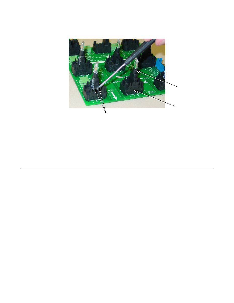
Twist the screwdriver just sufficiently to release the retainers while “rocking” the LED module in the socket.
Care must be exercised to avoid breaking off the delicate retaining tabs. If retaining tabs break off, then the complete PCB A3
should be replaced (see appendix F for part numbers).
Fig 7.2 Removing an LED
The new LED module (see appendix F for part numbers) is simply pushed firmly into the same location on the socket until the
retainers snap into place. Then reassemble the PCB A3 to the operator panel on the inside of the enclosure door, using the 9
screws previously removed.
This procedure is also employed to replace the Selector Switch modules on the “Bypass Operator Interface PCB A3”.
Replacing The Relay Controller PCB:
The Bypass controller relays are not individually replaceable, the “Bypass Relay Controller PCB A2” assembly must be
replaced (see appendix F for part numbers). The “Bypass Relay Controller PCB A2” is located on the left hand side of the wall
mount enclosure, adjacent to the door hinge.
To remove PCB A2, disconnect the ribbon cable connectors at CN102 A, CN102 B and CN103. Mark and disconnect the
wires from TB CN102 C as well as marking and disconnecting all field wiring from terminal block TB1.
Remove the 5 nuts securing the circuit board to the side wall of the enclosure, lift out and replace the “Bypass Relay Controller
PCB A2” assembly with a new one (see appendix F for part numbers).
LED Module Retaining Tabs
LED Socket
LED Module