Termination configuration - power wiring – Yaskawa E7B Drive Bypass User Manual
Page 40
Electrical Installation 2 - 2
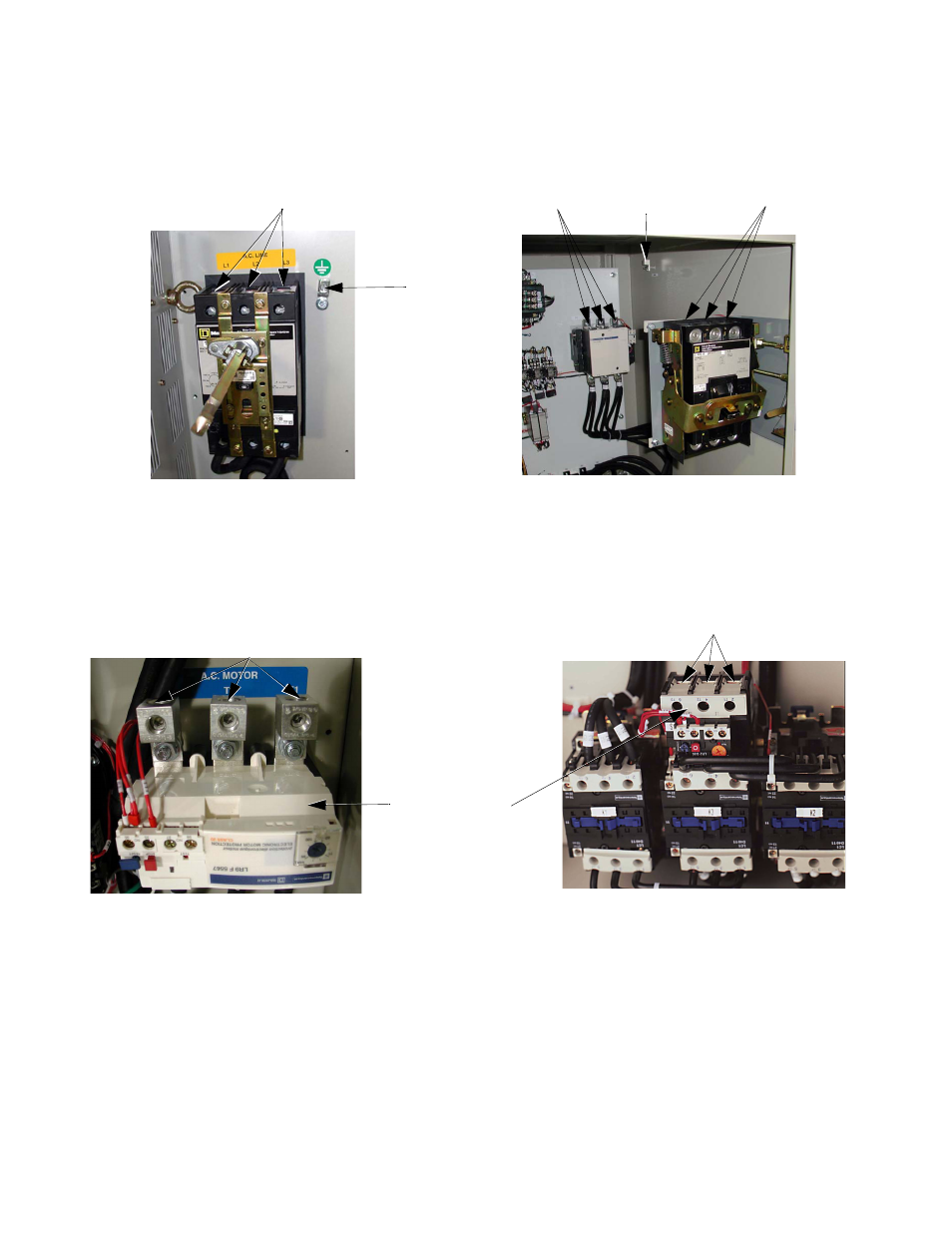
Termination Configuration - Power Wiring
The Circuit Breaker/MCP is located in the upper right hand side of the Bypass unit. The Bypass three phase input power
connection is made to the input terminals of the MCP. See Figure 2.1 and 2.2 for representative examples.
Fig 2.1 Typical Input Power Connection,
Fig. 2.2 Typical Input and Output Power
Wall Mount Unit
Connections, Floor Mount Unit
The OverLoad Relay (OLR) is mounted to the contactor assembly or back panel (depending on rating), just above the bypass
contactor. The Bypass three phase output power connection to the motor is made to the output terminals of the OverLoad
Relay. See Figure 2.3 for representative examples.
Fig 2.3 Typical Output Power Connection, Wall Mount Units
Overload Relay
Motor Connections
Input Power
Ground Lug
Ground Lug
Input Power
Motor
Connections
Motor Connections