Wire routing, Fig 2.5 wall mount enclosures, Drive main circuit configurations 208-240 vac – Yaskawa E7B Drive Bypass User Manual
Page 44: Table 2.2 drive main circuit configurations, Electrical installation 2 - 6
Advertising
Electrical Installation 2 - 6
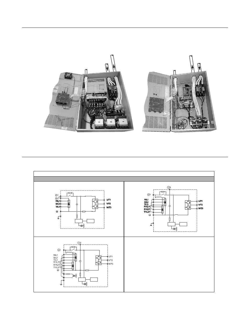
Wire Routing
The following Figures indicate suggested wire entry and bending areas for representative wall mount enclosures.
Typical Enclosure 2
Typical Enclosure 2
Fig 2.5 Wall Mount Enclosures
Drive Main Circuit Configurations 208-240 VAC
Table 2.2 Drive Main Circuit Configurations
208-240 VAC
---
Control
circuit
wiring
Control
circuit
wiring
Input
power
Input
power
Motor
connection
Motor
connection
Power
supply
Control
circuits
{
1
Note
CIMR-_ _ _ 20P4 to 2018
(1/2 Hp to 25 Hp)
Power
supply
Control
circuits
{
Notes
1 & 3
CIMR-_ _ _ 2022 and 2030 (30 Hp to 40 Hp)
CIMR-_ _ _ 2037 to 2110 (50 Hp to 150 Hp)
Power
supply
Control
circuits
{
Notes
1 & 3
Advertising