Physical installation 1 - 18 – Yaskawa E7B Drive Bypass User Manual
Page 30
Advertising
Physical Installation 1 - 18
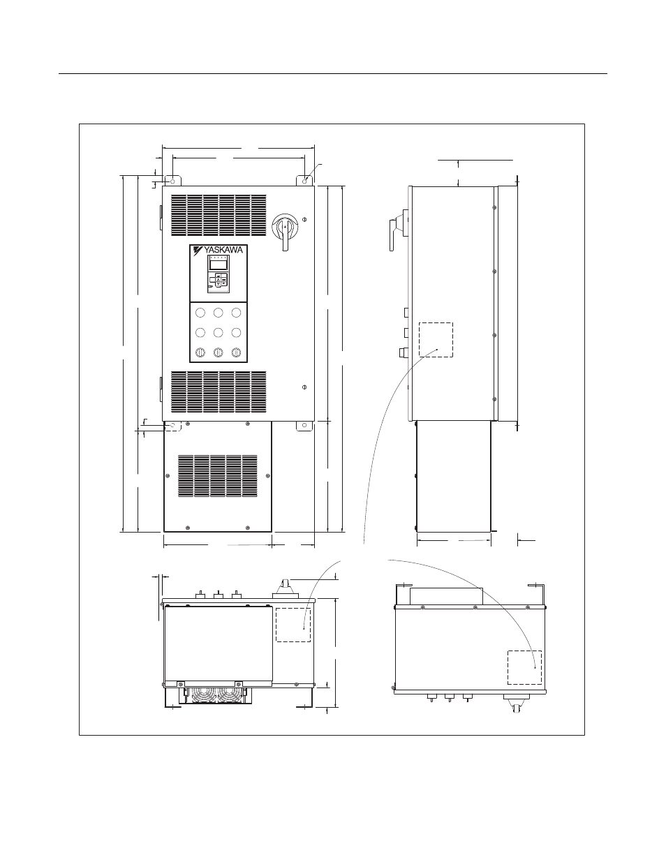
Bypass Unit 30 HP and Below, 480 VAC; 15 HP and Below, 208V/240V
With Add-On Box
Fig 1.11 Enclosure 1, with Options Extension, for up to 30HP, 480 VAC
NEMA 1 and NEMA 12 FVFF Enclosures
E7
BYPASS
NORMAL
TEST
SAFETIES FAULT
MOTOR OL/
DRIVE
PURGE
SMOKE
AUTO
HAND
OFF
FAULT
DRIVE
BYPASS
RUN
POWER ON
CONTROL
DRIVE
RUN
RUN
STOP
FWD
REV
SEQ
REF
ALARM
AUTO
Monitor
MENU
ESC
DATA
ENTER
RESET
32.00
(812.8)
0.75
(19)
0.75
(19)
Ø0.50(4PLS)
(Ø12.7)
13.50
(342.9)
16.50
(419.1)
1.29
(32.8)
5.37
(136.4)
19.06
(484.1)
12.60
(317.5)
44.60
(1132.8)
29.48
(748.8)
13.87
(3.81)
43.35
(1,101.2)
13.66
(347)
2.37
(60.2)
2.50
(63.5)
RECOMMENDED
CONDUIT
ENTRANCE AREA
TOP, BOTTOM
AND SIDE
MIN. 6
(152.4)
MIN. 1.50
(3.81)
DIMENSIONS IN INCHES (MM), FOR REFERENCE ONLY
9.1
3.375
(231.1)
(85.7)
TOP VIEW
Advertising