Control wiring, Bypass field control wire landing, Fig 2.6 tb1 control terminal locations, all models – Yaskawa E7B Drive Bypass User Manual
Page 46
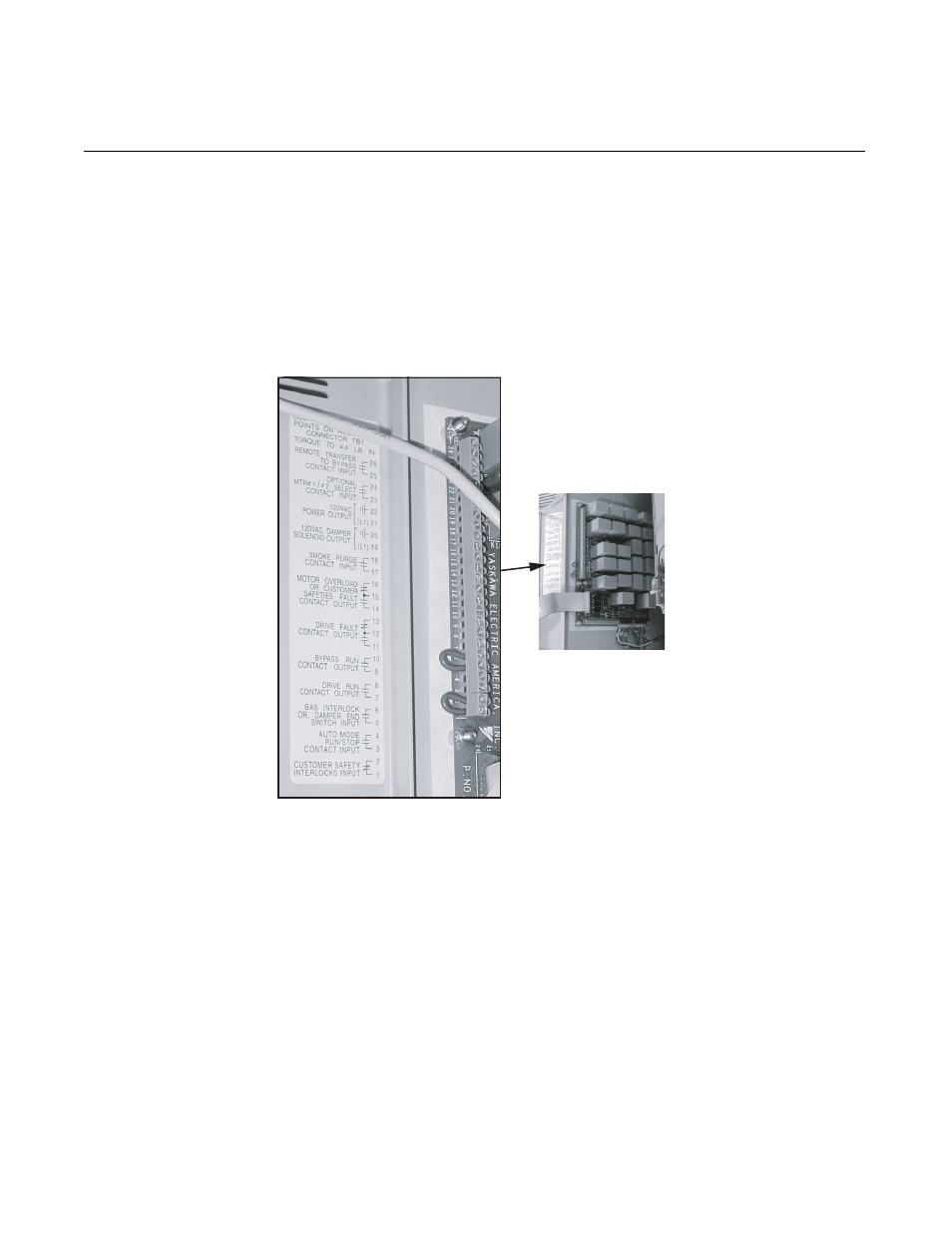
Electrical Installation 2 - 8
Control Wiring
Bypass Field Control Wire Landing
The Bypass field control wiring is terminated on the relay control PCB A2, Terminal block TB1. The terminal designations
are labeled on the door, adjacent to PCB A2 (see Figure 2.6). Route the control wiring as shown in Figure 2.5.
TB1 terminals 1 and 2 are jumpered (J1) as the unit is shipped from the factory. If a customer supplied series circuit of NC
safety devices is to be used, this jumper is removed and the safety circuit connected between terminals 1 and 2.
TB1 terminals 5 and 6 are jumpered (J2) as the unit is shipped from the factory. If customer supplied Drive NO enabling con-
tacts (open = Drive disabled, closed = Drive enabled) are to be used (such as a damper end switch or occupied cycle timer),
this jumper is removed and the enabling contacts wired between terminals 5 and 6.
Fig 2.6 TB1 Control Terminal Locations, All Models