Fig 4.2 typical mcp circuit breaker, Start up and operation 4 - 7 – Yaskawa E7B Drive Bypass User Manual
Page 89
Start Up and Operation 4 - 7
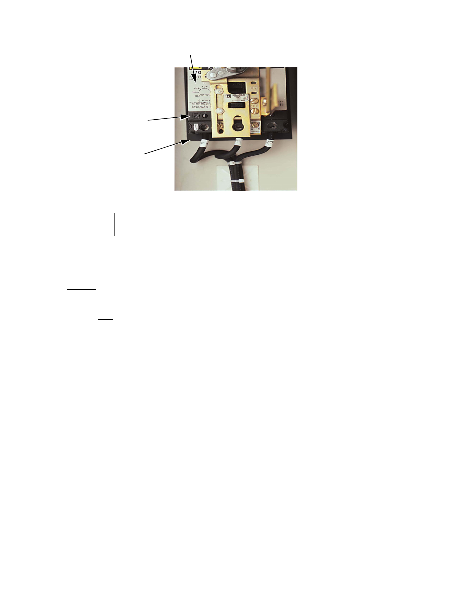
Fig 4.2 Typical MCP Circuit Breaker
13. Turn the HAND/OFF/AUTO switch to OFF and the DRIVE/BYPASS switch to BYPASS. The Drive will ramp the
motor to zero speed, then the Drive will be de-energized and control transferred to Bypass mode. Be prepared to
monitor the rotation direction of the motor in Bypass operation. “Bump” the HAND/OFF/AUTO switch to the
HAND position and quickly back to OFF. Check the motor rotation. Do not allow the motor to continue operating in
BYPASS until rotation is correct!
If the rotation direction in Bypass is correct, skip the rest of this step. If not, carry out the following corrections:
1.
Turn OFF the incoming power feed to the Drive. Since the correct rotation in Drive mode was previously
established, do not change any output wires at the motor.
2.
Instead, verify that power to the circuit breaker is OFF. Then swap L1 & L2 on the input side of the circuit
breaker/disconnect switch (CB1). This will affect rotation in Bypass operation only. Once connections are
complete and tight, reapply the incoming power and repeat the previous step to re-check the rotation direction in
Bypass mode.
14. Run the motor in Bypass by placing the HAND/OFF/AUTO switch in HAND. Record all the phase voltages and
currents at this time.
15. Select the OFF position of the HAND/OFF/AUTO switch and place the BYPASS/DRIVE switch in DRIVE. Turn to
the HAND position and scroll the Speed Command to “60 HZ” operation. Monitor the voltages and currents in each of
the output phases at full speed to make sure the voltages are balanced and the currents are within the motor nameplate
rating during accel, stable speed, and decel.
16. If this application requires the Drive to operate in PI mode, see Chapter 5.
17. For fan applications, with the HAND/OFF/AUTO switch set to AUTO, have the building automation system give the
Drive a run command and a speed command. Put the BYPASS/DRIVE switch into BYPASS and let the load speed up
and stabilize. Then move the switch to DRIVE. Observe if the DC braking is enough to stop the fan in the time period
set in parameter b2-03 (5 sec factory setting). If not, set this parameter to its maximum setting, which is 10.0 seconds.
If this is not enough, slowly increase the braking current setting (parameter b2-02) but do not go above 90% to protect
the Drive output devices.
For serial communication, refer to TM.E7.21 (APOGEE FLN) and TM.E7.22 (Metasys N2).
IMPORTANT
To maintain overcurrent, short-circuit, and ground-fault protection, the manufacturer’s instructions for
setting the instantaneous-trip circuit breaker must be followed.
Adjustment Dial Label
Trip Setting
Adjustment Dial
MCP