All voltages, Table c.3 common drive specifications, Specifications c - 4 – Yaskawa E7B Drive Bypass User Manual
Page 260
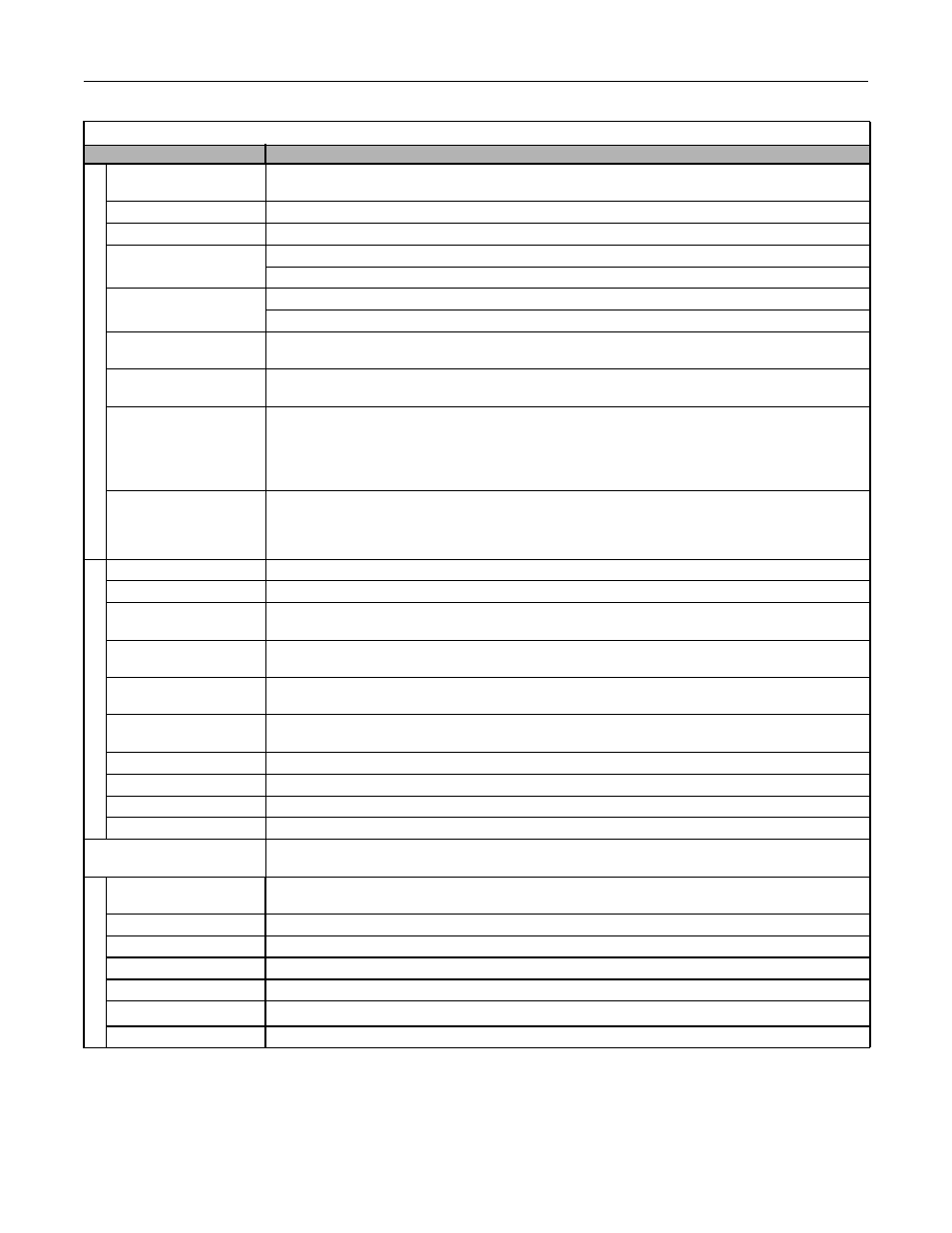
Specifications C - 4
All Voltages
Table C.3 Common Drive Specifications
All Models
Specification
Control method
Sine wave PWM
V/f control
Speed range
40:1
Speed control accuracy
±2 to 3% (77
°F ± 50°F) (25°C ± 10°C)
Frequency accuracy
(temperature characteristics)
Digital references: ± 0.01% (14
°F to 104°F) (-10°C to +40°C)
Analog references: ±0.1% (77
°F ± 50°F) (25°C ±10°C)
Frequency setting resolution
Digital references: 0.01 Hz
Analog references: 0.025/50 Hz (10 bit with sign)
Frequency setting signal
(Speed Command)
0-10 Vdc, 4-20 mA
Acceleration/Deceleration
time
0.0 to 6000.0 s (2 selectable combinations of independent acceleration and deceleration settings)
Main Drive control
functions
Restarting for momentary power loss, bi-directional speed search, overtorque detection, 5 preset speeds,
acceleration/deceleration time changes, S-curve acceleration, 3-wire sequence, auto-tuning, cooling fan ON/OFF con-
trol, torque compensation, jump frequencies, upper and lower limits for frequency references, DC braking for starting
and stopping, high-slip braking, PI control (with sleep function), energy-saving control, Modbus communications (RS-
485/422, 19.2 kbps maximum), fault reset, and copy function
Main Bypass control
functions
Provides an alternate connection for the motor to line power for operation at full speed only, directly from line power.
Three electrically interlocked IEC rated contactors isolate the Drive when operating in Bypass mode. Control logic cir-
cuit provides Hand/Off/Auto functions and safety circuit interlocks. Includes fused 120VAC control transformer, motor
circuit protector/disconnect, motor overload relay, selector switches and indicating lights.
Motor protection
Protection by electronic thermal overload relay
Fuse blown protection
Stops for fuse blown
Overload capacity and
maximum current
110% of rated output current for 60 seconds
Overvoltage protection
208-240VAC: Stops when main-circuit DC voltage is above 410 V
480VAC: Stops when main-circuit DC voltage is above 820 V
Undervoltage protection
208-240VAC: Stops when main-circuit DC voltage is below 190 V
480VAC: Stops when main-circuit DC voltage is below 380 V
Momentary power loss
ride thru
Power Interuptions of 15 ms or more
By selecting the momentary power loss method, operation can be continued if power is restored within 2 s
Cooling fin overheating
Protection by thermistor
Stall prevention
Stall prevention during acceleration, deceleration, or running
Grounding protection
Protection by electronic circuits. (50% of inverter rated current)
Charge indicator
Lit when the main circuit DC voltage is approx. 50 Vdc or more
Enclosure Type
Enclosed wall-mounted type (NEMA 1): CIMR-E7U20P4 thru 2030 and 40P4 thru 4055
Open chassis type (IP00):
CIMR-E7U2022 thru 2110 and 4030 thru 4300
Ambient operating
temperature
14
°F to 104°F (-10°C to 40°C) NEMA 1 type
14
°F to 113°F (–10°C to 45°C) Open chassis type
Ambient operating humidity
95% max. (with no condensation)
Storage temperature
-4
°F to 140°F (- 20°C to + 60°C) short-term temperature during transportation
Application site
Indoor (no corrosive gas, dust, etc.)
Altitude
3300 ft. (1000 m), higher altitudes by derate
Vibration
10 to 20 Hz, 32 ft/sec
2
(9.8 m/s
2
) max.; 20 to 50 Hz, 6.5 ft/sec
2
(2 m/s
2
) max.
Appraisal Agencies
UL File E143427
Prot
ecti
ve Functi
ons
Co
nt
ro
l Ch
arac
te
ris
tic
s
Env
ironm
ent