Bypass unit start up procedure, Fig 4.1 typical motor overload and contactors – Yaskawa E7B Drive Bypass User Manual
Page 86
Start Up and Operation 4 - 4
BYPASS UNIT START UP PROCEDURE
(Please review “Bypass Start Up Preparation” on page 4-3)
1. Before applying power, make sure that the following conditions are met:
•
The DRIVE/BYPASS switch is in the DRIVE position.
•
The HAND/OFF/AUTO switch is in the OFF position.
•
The NORMAL/TEST switch is in the NORMAL position. [Note: If the TEST position is selected while the
DRIVE/BYPASS switch is in the DRIVE position, the fault code “UV, DC Bus Undervolt” will be briefly
displayed and the Drive will shut down. TEST mode is only available when in the BYPASS position.]
•
The VAV terminal unit dampers, in supply fan applications, are open to prevent duct flexing or damage in a full
speed, across the line starting situation.
•
The electro-mechanical motor OverLoad Relay (OLR) (S10) is adjusted to equal the Full Load Amps (FLA) value
from the motor nameplate.
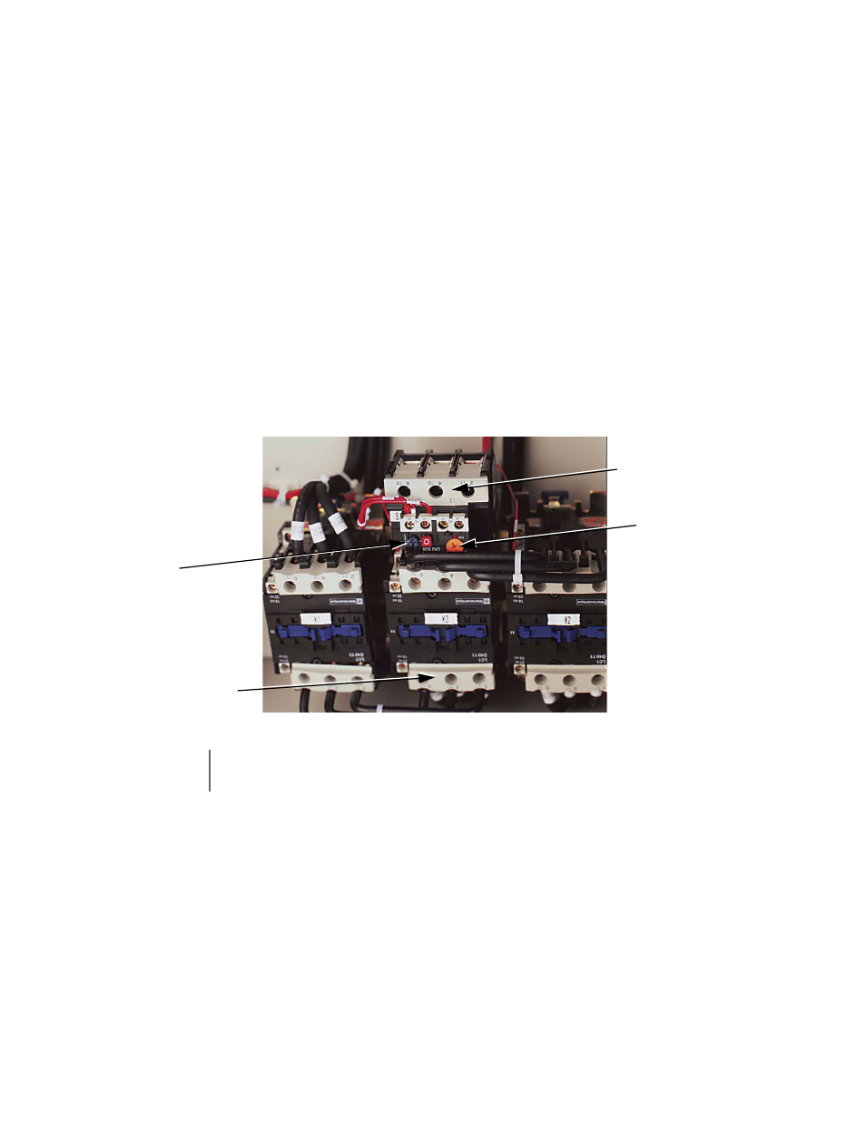
The OLR is mounted to the contactor assembly or back panel (depending on rating), just above the Bypass contactor.
See Figure 4.1. Electrically on the output power side of the Bypass unit, the adjustable thermal OLR provides overload
protection for the motor in both the Drive and Bypass operating modes. The OLR is set up in the factory to be a
manual reset device, requiring operator attention if an overload trip-out is experienced.
Fig 4.1 Typical Motor Overload and Contactors
2. Apply power to the Drive and Bypass package. Ensure that all three phases are present and that the input voltage is
correct for the system being set up. The CONTROL POWER ON, STOP and AUTO SEQ and REF LEDs on the
control panel should be ON and the display will be in the “-DRIVE-/Operation” menu showing the active speed
command. [Note: If the MOTOR OL/SAFETIES FAULT light is ON, press the reset button on the motor OLR (S10)
and check the “safety device” circuit between terminals TB1-1 and TB1-2.].
IMPORTANT
To maintain overcurrent, short-circuit, and ground-fault protection, the manufacturer’s instructions for
setting the motor OLR must be followed.
OverLoad Relay
Bypass Contactor
Adjustment Dial
Reset Button