ProSoft Technology PS69-DPM User Manual
Page 106
Contents
PS69-DPM ♦ CompactLogix or MicroLogix Platform
User Manual
PROFIBUS DPV1 Master
Page 106 of 130
ProSoft Technology, Inc.
October 1, 2014
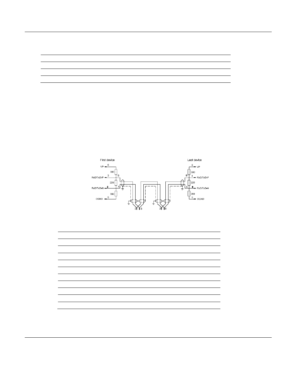
6.1.2 PROFIBUS Interface
Isolated RS-485 interface per EN 50170.
3
RxD/TxD-P
Receive/Send Data-P respectively connection B plug
5
DGND
Reference potential
6
VP
Positive power supply
8
RxD/TxD-N
Receive/Send Data-N respectively connection A plug
Please ensure that termination resistors are available at both ends of the cable. If special
PROFIBUS connectors are being used, these resistors are often found inside the connector
and must be switched on. For baud rates above 1.5 MBaud use only PROFIBUS
connectors, which also include additional inductance. It is not permitted to have T stubs at
high baud rates.
Use only a special cable which is approved for PROFIBUS-DP. Make a solid connection
from the cable shield to ground at every device and make sure that there is no potential
difference between the grounds at the devices.
If the PS69 is linked with only one other device on the bus, both devices must be at the ends
of the bus line. The reason is that these devices must deliver the power supply for the
termination resistors. Otherwise the Master can be connected at any desired position.
6.1.3 Functional Specifications
Specification
Description
Slaves
max. 125
Input/Output
max. 244 Bytes per Slave
Input Data
max. 408 Bytes (*)
Acyclic Data
DPV1
Status data
88 Bytes
Output data
max. 480 Bytes (*)
Command data
16 Bytes
DPV1 services
Read / Write class 1, Alarm
Services
Global-Control, Slave-Diag, Set-Parameter
Sync, Freeze Command
supported
Up to 32 PROFIBUS devices can be connected to one bus segment. If several bus
segments are linked to each other with repeaters, there can be up to 127 devices on the
network.