ProSoft Technology PS69-DPM User Manual
Page 53
PS69-DPM ♦ CompactLogix or MicroLogix Platform
Contents
PROFIBUS DPV1 Master
User Manual
ProSoft Technology, Inc.
Page 53 of 130
October 1, 2014
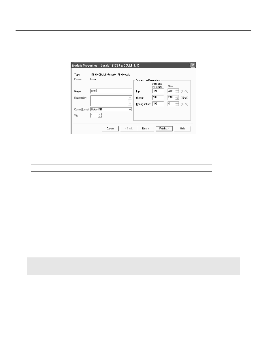
2.3.2 Module Properties 1
The communications parameters for the module should be set as shown in the dialog below.
Determine a name and enter a short description of the module. Select the slot number in
which the module is installed in the controller. Select Data - INT as the Comm_Format. Set
the connection parameters as they are shown in the dialog.
Connection Parameter
Assembly Instance
Size (in Words)
Input
101
44 + X (X = 0 ... 204)
Output
100
8 + Y (Y = 0 ... 240)
Configuration
102
0
X = Number of Words configured for the Master module (PROFIBUS input data); input size can be in the range
between 44 and 248 words
Y = Number of Words configured for the Master module (PROFIBUS output data); output size can be in the
range between 8 and 248 words
Input Size: The input size must be at least 88 Bytes (44 Words). It must be large enough
to accommodate the status information required by the module, which is 88 Bytes (44
Words) and the number of PROFIBUS input data. You can increase the size of this area
using the size of each Input module connected. The Input image starts with byte 88.
Output Size: The output size must be at least 16 Bytes (8 Words). It must be large
enough to accommodate the command information required by the module, which is 16
bytes (8 Words), and the number of PROFIBUS output data. You can increase the size
of this area using the size of each Output module connected. The Output image starts
with byte 16.
Note: If the parameters do not correspond to the template values, then the controller cannot establish a
communication relationship with the module.
Select Next > for the next configuration dialog.