Port type, Port type –4 – Altera SerialLite II IP Core User Manual
Page 27
3–4
Chapter 3: Parameter Settings
Physical Layer Configuration
SerialLite II MegaCore Function
January 2014
Altera Corporation
User Guide
■
If you select a reference clock frequency that is not equal to the
data rate/(transfer size) * 10, the Clock Compensation option is disabled if the
Receiver only
port type option is turned on.
Port Type
The Port Type parameter offers three options: Bidirectional, Transmitter only, and
Receiver only
. If you turn on the Bidirectional option, you must specify values for
Transmitter Settings
and Receiver Settings. Under Transmitter Settings, you need to
specify the Number of lanes, and select whether or not to enable the Scramble and
Broadcast mode
. Under Receiver Settings, you must specify the settings for the
Number of lanes
, and select whether or not to enable the De-Scramble option. If you
turn on Transmitter only option, you must specify values for Transmitter Settings
only
, and if you turn on Receiver only option, you must specify values for Receiver
Settings
only.
The Number of lanes parameter dictates the number of serial links, essentially the
number of external inputs and outputs (I/Os) for the MegaCore function.
If you set the Number of lanes for the transmitter and receiver settings to the same
value, you configure the MegaCore function to operate in symmetric, bidirectional
mode. Refer to
and
.
If you set the Port Type to Receiver only or Transmitter only, you configure the
MegaCore function to operate in unidirectional mode, transmitter, or receiver only.
Refer to
and
on page
.
If you set the Port Type to Bidirectional, but have the number of lanes set to a value
other than zero, but not equal to the other function’s value, you configure the
MegaCore function to operate in asymmetric mode. Refer to
on page
.
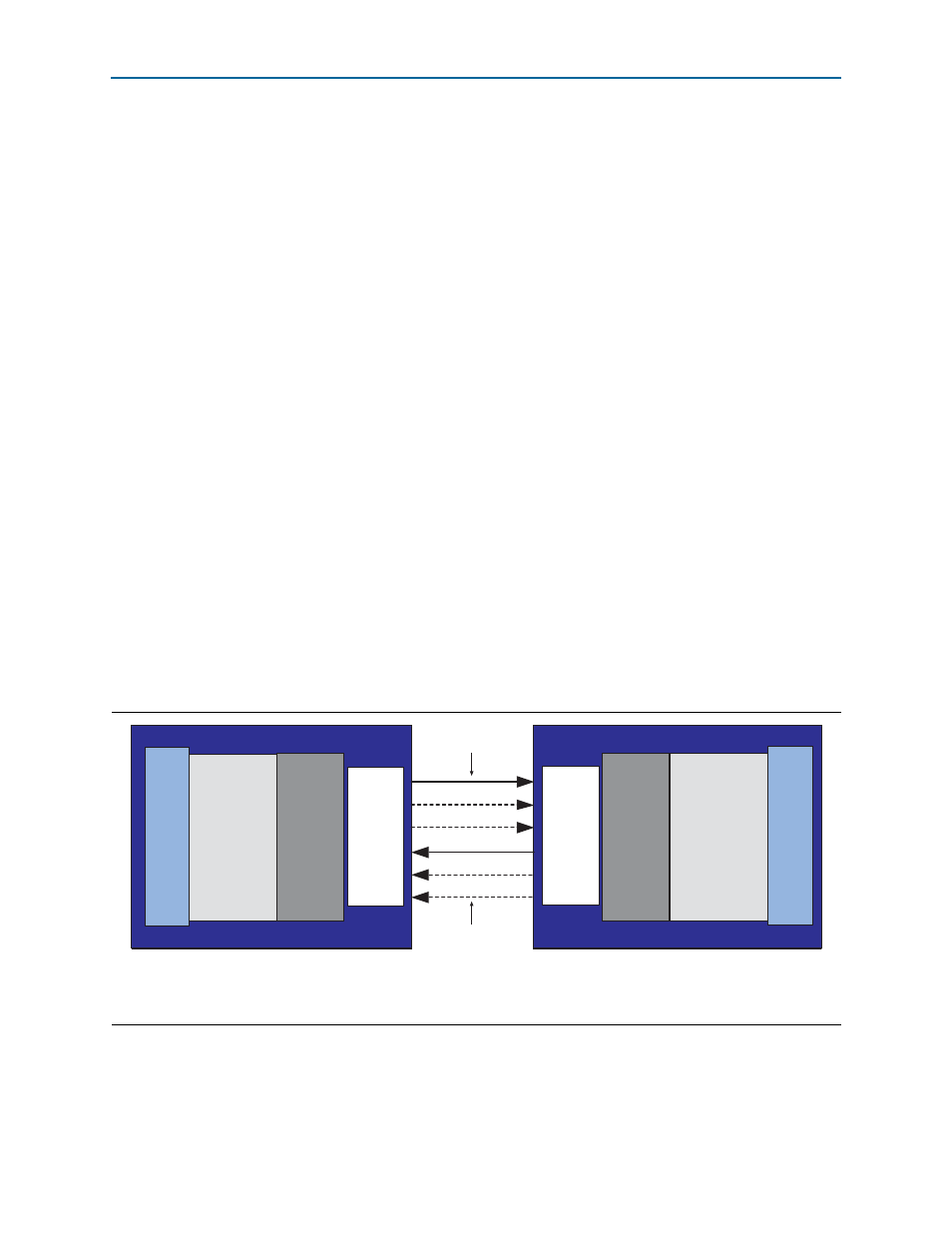
Figure 3–2. Symmetric Mode Block Diagram
Notes to
(1) A full line indicates a mandatory lane.
(2) A dashed line indicates an optional lane.
One or more lanes
(up to N)
FPGA 1
Light-weight
Linklayer
PHY
Layer
FPGA 2
Light-weight
Linklayer
PHY
Layer
Atlantic
Interface
CDR
SERDES
CDR
SERDES
One or more lanes
(up to N)
Atlantic
Interface