Altera SerialLite II IP Core User Manual
Page 42
Chapter 3: Parameter Settings
3–19
Link Layer Configuration
January 2014
Altera Corporation
SerialLite II MegaCore Function
User Guide
To calculate latency numbers in terms of time units, multiply the latency values in
by the tx_coreclock clock period.
The Threshold parameter must be set to a value such that the FIFO does not
completely empty during a flow control operation (this can cause inefficiencies in the
system), and leave enough room in the FIFO to ensure any remaining data in the
system can be safely stored in the FIFO without the FIFO overflowing.
The proper threshold value can be derived by subtracting the depth of the FIFO from
the total latency.
Total Latency = [tlate_fc_transmit + t_wd + tlate_fc_receive +
tlate_stop_data]
cycles
1
The ratio between one element and one cycle is equal to one. When you write one
element to the FIFO, it takes one clock cycle. Therefore one cycle is one element.
Therefore, the Threshold value should be set based on the following formula:
Threshold value = Total Depth of FIFO (elements) - Total Latency (clock cycles)]
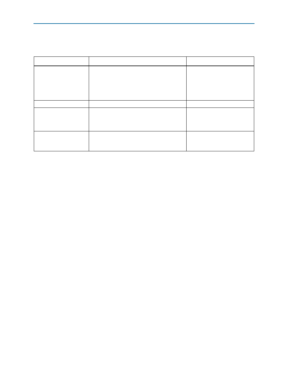
Table 3–6. SerialLite II Flow Control Internal Latency
Internal Latency
Description
Latency Value (cycles)
tlate_fc_transmit
Latency that occurs during RX FIFO breach up to the
point where the associated flow control link
management packet is sent out on the link. This
includes the time for the core to generate the link
management packet and the time through the
transceiver.
24
t_wd
Wire delay
tlate_fc_receive
Latency that occurs in the duration when the flow
control link management packet reaches the
transceiver pins until the the core processes the
request.
23 + deskew cycles
tlate_stop_data
Overall system core latency (indicates the amount of
data that may still be in the system when the PAUSE
begins). This data must still be stored in the RX FIFO.
Regular data: 41
Priority data: 41 + seg_TX
+
seg_RX
Notes to
(1) t_wd specifies the wire delay between the devices. This value depends on the data rate and trace lengths in the application.
(2) deskew cycles = 0 for single lane configuration;
deskew cycles = worst case lane to lane skew in the transceiver, refer to
“SerialLite II Deskew Support” on page 4–6
(3) seg_TX and seg_RX are taken into account only for priority packets with retry-on-error feature. If a priority packet with retry-on-error feature
is in transfer, flow control begins immediately after the current segment of the priority packet has been sent.
seg_TX = [segment size/(TSIZE* TX_NUMBER_LANES)]
seg_RX = [segment size/(TSIZE* RX_NUMBER_LANES)]
The Segment size value is specified by users in the Parameters Settings tab on the Link Layer page.