Signals, Signals –22 – Altera SerialLite II IP Core User Manual
Page 76
4–22
Chapter 4: Functional Description
Signals
SerialLite II MegaCore Function
January 2014
Altera Corporation
User Guide
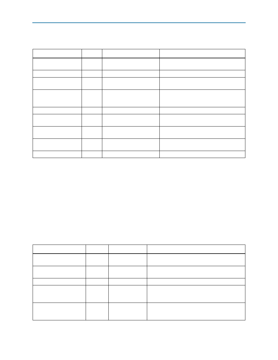
lists the new interface signals.
Some transceiver signals are removed due to the exclusion of hard transceiver in this
configuration. Refer to the next section for a more detailed description of the signals.
Signals
through
show the SerialLite II MegaCore function signals.
1
The signals required for a given configuration, as well as the appropriate bus widths,
are created automatically by the SerialLite II parameter editor based upon the
parameter values you select.
shows the high-speed serial interface signals.
Table 4–4. New Interface Signals
Signal Name
Direction
Width
Description
rx_parallel_data_out
Input
(Datapath width) x (Number of
receiver channels)
Data input from the hard receiver.
rx_coreclk
Input
1
Clock input from the hard receiver.
tx_parallel_data_in
Output
(Datapath width) x (Number of
transmitter channels)
Data output for the hard transmitter.
tx_ctrlenable
Output
(Number of control bits) x
(Number of transmitter
channels)
Control signal to indicate the control word in
tx_parallel_data_in
signal.
tx_coreclk
Input
1
Clock input from the hard transmitter.
rx_ctrldetect
Output
(Number of control bits) x
(Number of receiver channels)
Control signal to indicate that control word is
detected in the hard transceiver.
stat_rr_pattdet
Input
(Number of control bits) x
(Number of receiver channels)
Pattern detect output for the hard transceiver.
err_rr_disp
Input
(Number of control bits) x
(Number of receiver channels)
Disparity error output for the hard transceiver.
flip_polarity
Output
Number of receiver channels
Polarity inversion input for the hard transceiver.
Table 4–5. High-Speed Serial Interface Signals (Part 1 of 2)
Signal
Direction
Clock Domain
Description
rxin[
n-1]
,
Output
—
SerialLite II differential receive data bus. Bus carries
packets, cells, or in-band control words.
txout[
,
Output
—
SerialLite II differential transmit data bus. Bus carries
packets, cells, or in-band control words.
rrefclk
Output
rrefclk
Receive core output PLL-derived clock.
trefclk
Input
trefclk
Reference clock used to drive the transmitter PLL. The
PLL is used to generate the transmit core clock
(tx_coreclock).
tx_coreclock
Output
tx_coreclock
Transmitter core output clock. In Arria II GX and
Stratix IV designs, the TX PLL output clock and the
primary clock are used for the TX logic.