Figure 3–3, Figure 3–4 – Altera SerialLite II IP Core User Manual
Page 28
Advertising
Chapter 3: Parameter Settings
3–5
Physical Layer Configuration
January 2014
Altera Corporation
SerialLite II MegaCore Function
User Guide
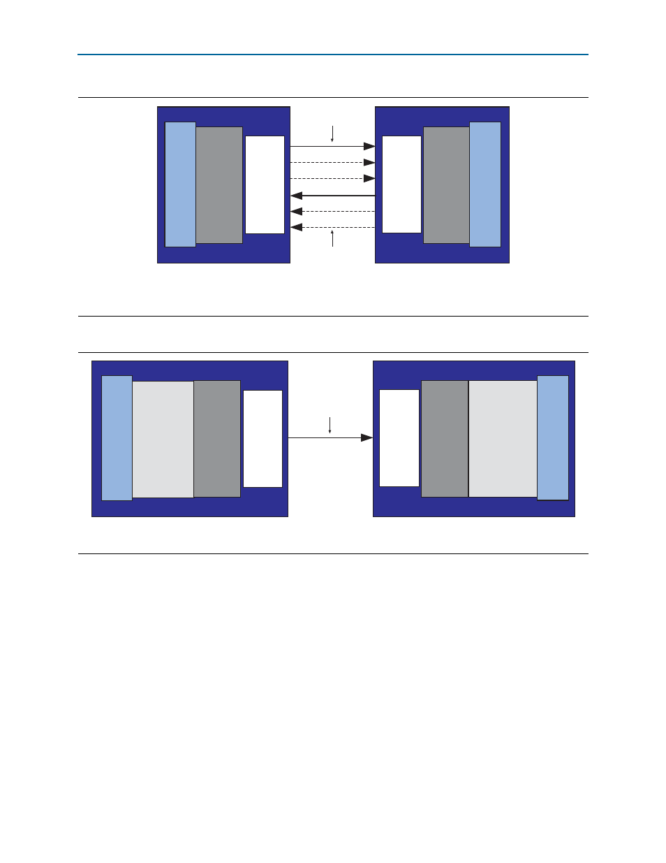
Figure 3–3. Streaming Symmetric Mode Block Diagram
Notes to
(1) A full line indicates a mandatory lane.
(2) A dashed line indicates an optional lane.
One or more lanes
(up to N)
FPGA 1
PHY
Layer
FPGA 2
PHY
Layer
Atlantic
Interface
CDR
SERDES
CDR
SERDES
One or more lanes
(up to N)
Atlantic
Interface
Figure 3–4. Simplex Mode Block Diagram
Note to
(1) A full line indicates a mandatory lane.
One lane only
FPGA 1
Light-weight
Linklayer
PHY
Layer
FPGA 2
Light-weight
Linklayer
PHY
Layer
Atlantic
Interface
CDR
SERDES
CDR
SERDES
Atlantic
Interface
Advertising