Self synchronized link up, Self synchronized link up –7, Figure 3–7 – Altera SerialLite II IP Core User Manual
Page 30
Chapter 3: Parameter Settings
3–7
Physical Layer Configuration
January 2014
Altera Corporation
SerialLite II MegaCore Function
User Guide
Self Synchronized Link Up
The receiver on the far end must synchronize itself to incoming data streams. To do so,
it uses the self-synchronizing LSM, a light-weight implementation that is especially
useful when data is streaming. As there is no handshaking or exchange of status
information between the receiver and transmitter, this parameter uses considerably
fewer logic elements than the full-duplex LSM. The self-synchronizing LSM can be
used in all modes, except asymmetric mode, but this mode can only support one lane.
This parameter is enabled by default when the MegaCore function operates in
unidirectional mode because the duplex LSM cannot be used when there is no return
path.
The ctrl_tc_force_train signal must be asserted for the training patterns to be sent.
Negate the signal once the adjacent receiver has locked, if this status information can
be made available, or after a user-defined period of time when the link status of the
adjacent receiver is not known or cannot be known. The LSM links up after receiving
64 consecutive valid, error-free characters. The link goes down after receiving four
consecutive errors; at this time, the ctrl_tc_force_train signal should be reasserted
until the receiver relocks.
The required hold time for the ctrl_tc_force_train signal largely depends on when
the ALTGX megafunction completes the power-on reset cycle. Therefore, the self-
synchronizing link-up state machine does not look at the incoming stream until the
transceiver reset is complete.
For example, the following procedure shows the transceiver reset sequence in an
Arria or Stratix transceiver device:
1. Wait for the pll_locked signal (stat_tc_pll_locked) to be asserted, which
happens when the PLL in the ALTGX megafunction locks to the reference clock
(trefclk). The reference clock must be characterized; 10 ms or less is normal.
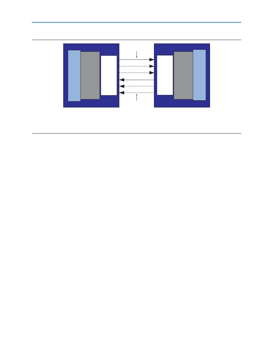
Figure 3–7. Streaming Asymmetric Mode Block Diagram
Notes to
(1) A full line indicates a mandatory lane.
(2) A dashed line indicates an optional lane.
One or more lanes
(up to N)
FPGA 1
PHY
Layer
FPGA 2
PHY
Layer
Atlantic
Interface
CDR
SERDES
CDR
SERDES
One or more lanes
(up to M, but
not equal to N)
Atlantic
Interface