High-speed serial interface, High-speed serial interface –3 – Altera SerialLite II IP Core User Manual
Page 57
Chapter 4: Functional Description
4–3
Interface Overview
January 2014
Altera Corporation
SerialLite II MegaCore Function
User Guide
On the transmitter side, the user input data packets are sent to the Atlantic interface
once the txrdp_ena signal is asserted (txrdp_ena pin is level triggered). The data
packets go through several internal processes in the SerialLite II data link layer and
physical layer, including all packet framing, CRC, and 8B/10B generation, and bit
serializing. These internal processes produce some core latency of approximately 21
clock cycles to finally send the packets to the High Speed Serial Interface (HSSI) link.
The latency calculation is based on the tx_coreclock frequency and is counted from
the first data presented at the Atlantic interface on the transmitter side to the first data
that appeared at the HSSI.
On the receiver side, the data packets are transmitted through the HSSI link and go
through another SerialLite II MegaCore function. In the other SerialLite II MegaCore
function, the same reverse processes are done in the SerialLite II data link layer and
physical layer to strip off the framing and return the raw data back in the Atlantic
interface. The data are presented at the Atlantic interface after approximately 25 clock
cycles of latency. The latency is counted from the first data that appeared at the HSSI
to the first data that reaches the Atlantic interface on the receiver side.
The Atlantic interface signals are described in
.
1
However, these latencies are based on the simulations and parameters set in the
testbench. The latencies vary depending on different designs and implementations,
and the fill levels of the Atlantic FIFO buffer in designs where the fill levels are used.
f
For more information on this interface, refer to the
High-Speed Serial Interface
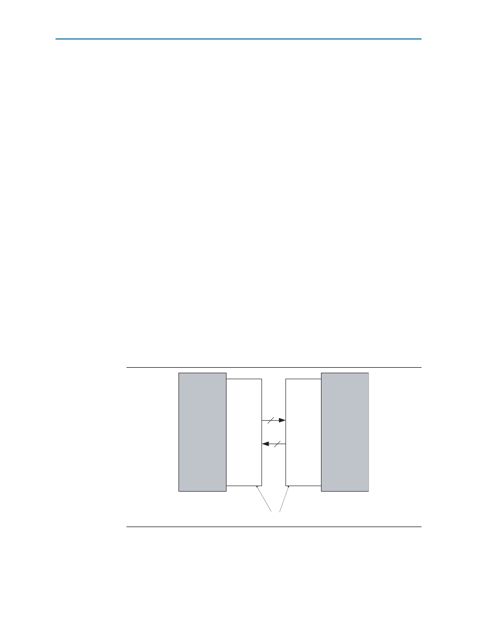
The high-speed serial interface always appears at the external device pins. The high-
speed interface consists of the differential signals that carry the high-speed data
between the two ends of a link, as shown in
The high-speed serial interface signals are detailed in
.
Figure 4–3. High-Speed Serial Interface Connections
SerialLite II
MegaCore
(Near)
SerialLite II
(Remote)
txout
rxin
rxin
txout
Function
MegaCore
Function
High-Speed Serial Interface