Safety barriers, Impact and trapping points, Hazards from expelling a part or attached tooling – Adept Python User Manual
Page 28: Table 2-3
Chapter 2 - Safety
28
Adept Python Modules User’s Guide, Rev. E
Safety Barriers
Safety barriers must be an integral part of robot workcell design. Adept systems are
computer-controlled and may activate remote devices under program control at times or
along paths not anticipated by personnel. It is critical that safeguards be in place to
prevent personnel from entering the workcell whenever equipment power is present.
The robot system integrator, or end user, must ensure that adequate safeguards, safety
barriers, light curtains, safety gates, safety floor mats, etc., will be installed. The robot
workcell must be designed according to the applicable local and national standards (see
The safe distance to the robot depends on the height of the safety fence. The height and
the distance of the safety fence from the robot must ensure that personnel cannot reach the
danger zone of the robot (see
).
The Adept control system has features that aid the user in constructing system
safeguards, including customer emergency stop circuitry and digital input and output
lines. The emergency power-off circuitry is capable of switching external power systems,
and can be interfaced to the appropriate user-supplied safeguards.
Impact and Trapping Points
The modules are capable of moving at high speeds. If a person is struck by a robot
(impacted) or trapped (pinched), death or serious injury could occur. System
configuration, joint speed, joint orientation, and attached payload all contribute to the
total amount of energy available to cause injury.
Hazards From Expelling a Part or Attached Tooling
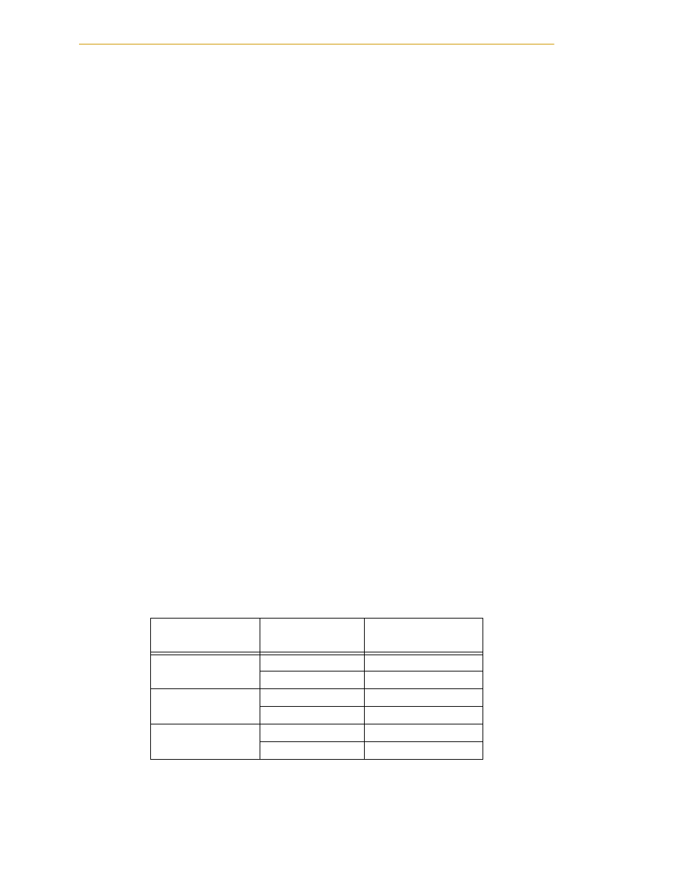
The maximum joint tip speeds that can be achieved by Adept Python Modules in a
runaway
situation are listed in
. Any tooling, fixtures, end-effectors, etc.,
mounted to the module must be attached by sufficient means to resist being expelled from
the module. Additionally, any payload must be held by the end-effector in a manner that
prevents the payload from being expelled accidentally.
a
See module product specifications for maximum rated thrust
that can be applied repeatedly in an application. The values
listed in the table above are for safety considerations.
Table 2-3. Maximum Linear Modules Joint Velocities in Runaway Situations
a
a
These velocities can occur only in a runaway or mechanical
failure situation. These are not performance specifications.
Module Type
Lead type,
mm/rev
Max linear speed
(mm/s)
L18
10
979
20
1940
L12
10
979
20
1940
L08
10
1170
20
2340