Daktronics AB-1600-1.5,2.5 User Manual
Page 10
1-4
Introduction
1.3 Display
Definitions
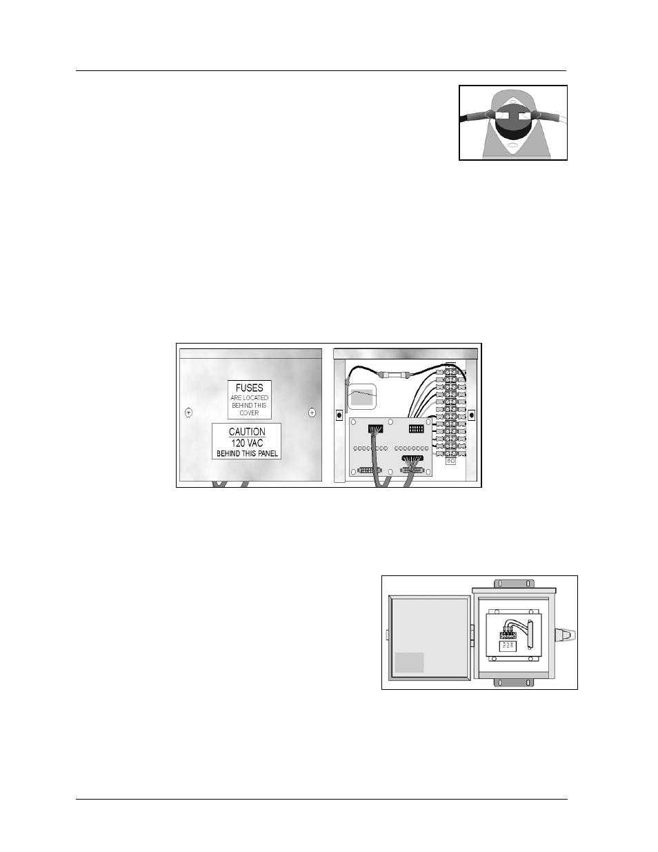
Button Thermostats: Small, round, nickel-size thermostats mounted within
the display on the transformers. The master-echo board within the fan
controller enclosure monitors these thermostats. Figure 5 shows a button
thermostat.
Controller Computer: The computer used to program the display. This
display will use either Venus 1500 or Venus 4600 software.
Display Controller: A general term used to describe the device housed within the display cabinet that
receives signal from the controller computer. This display will use as a controller either 1) a Venus
1500 controller or 2) a serial line interface.
Fan Controller Enclosure: Assembly found within the display that serves as a junction point for the
button thermostats. Venus 1500 systems will also have a master-echo board with in the enclosure.
Venus 4600 systems have no master-echo board within the fan controller enclosure, but instead route
the thermostat status back to the serial line interface board. Figure 6 shows the fan controller
enclosure, both with and without the enclosure cover. The master-echo board is on the right. The
Venus 4600 fan control enclosure looks similar, but lacks the master/echo board.
Fiber Optic: A standard communication method using light (signal) transmitted through a glass fiber.
Fiber optic cable cannot exceed 1,200 feet. A signal converter may be required for fiber optic and
RS/232 configuration. This communication method is an option in both Venus 1500 and Venus 4600
Systems.
Junction Box: Small enclosure in which display data
traveling on serial cable from the computer is transferred to
RS/232 cable. The junction box must be located within 25
feet of the display. Only Venus 1500 systems using the
RS/232 communication option utilize this junction box.
Figure 7 illustrates a junction box.
Figure 5: Button
Thermostat
Figure 6: Fan Controller Enclosure
Figure 7: Junction Box