Daktronics AB-1600-1.5,2.5 User Manual
Page 45
Maintenance & Troubleshooting
4-3
controller can flip the relay, turning off the fans and extending the life of both the fans and the
filters. Replace this fuse only with an AGC-7 1/2, 7 1/2 A, 250V fuse.
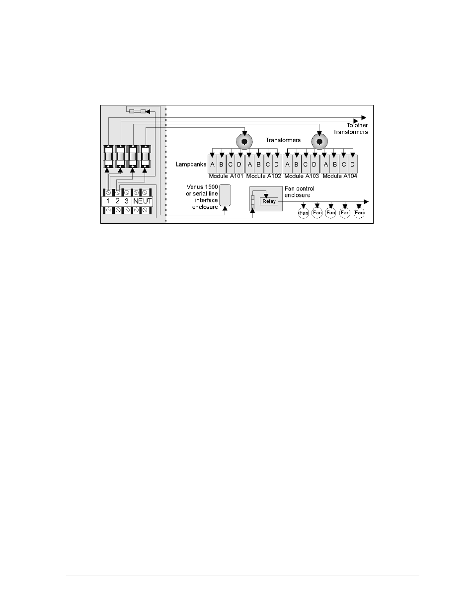
Figure 42 provides a general summary of the power routing of the 1600 series small matrix
displays. Neutral and ground wires are not illustrated. The illustration is for conceptual purposes
only.
For detailed power and signal information, refer to the appropriate general schematic at the end of
this section, or the project specific schematic in Appendix A, if one was included. Refer to
Section 4.2 if unsure which schematic to use.
Signal Summary
Because they use different display controllers, Venus 1500 and Venus 4600 systems differ
significantly in terms of signal routing. For this reason, the signal routing of each is addressed
separately within this sub-section.
Venus 1500 Signal Summary
Venus 1500 systems are comprised of a computer running Venus 1500 software that sends
data to a Venus 1500 display controller within the display. The controller computer can send
data to the display controller in any of the following signal formats.
•
RS/232
•
RS/422
•
Modem
•
Fiber Optic
Each of the previously listed signal formats requires slightly different cable and controller
equipment. Figure 3 in Section 1.2 illustrates the various Venus 1500 system configurations.
For more detailed information regarding controller computer to display controller connection,
refer to the schematic appropriate for this display (Section 4.2) and the Section 3 instructions
for bringing signal to the display.
After receiving data from the controller computer, the Venus 1500 controller then relays the
display information to the master-echo board within the fan controller enclosure. A 20-pin
cable connects J3 on the Venus 1500 controller to J1 (Controller Input) on the master-echo
board.
Figure 42: Power Routing Example