Daktronics AB-1600-1.5,2.5 User Manual
Page 55
Maintenance & Troubleshooting
4-13
Complete the following steps to remove a vertical shift board.
1. Remove the appropriate lens/reflector assembly as explained in Lens/Reflector Assemblies in
Section 4.3.
2. Disconnect any remaining signal cables from the vertical shift board.
3. Remove the nut holding the board in place.
4. Remove the board from the lampbank.
Complete the following steps to replace a vertical shift board.
1. Remount the vertical shift board to the lampbank and secure it with the nut.
2. Reattach the signal cable running between J1 (Data Out) and J2 (Input) on the underlying
lampbank.
3. Reinstall the lens/reflector assembly as explained in Lens/Reflector Assemblies in Section
4.3.
Fans
Fans are critical components of this display system. Generally, there is one fan for every three
modules. Do not run this display if even one fan is inoperable.
After replacing 10 percent of the fans, Daktronics recommends replacing all the fans to reduce
additional maintenance costs resulting from inefficient fan operation.
Refer to Section 4.8 for fan maintenance information and to Section 4.15 for the part number of
the fans used in this display.
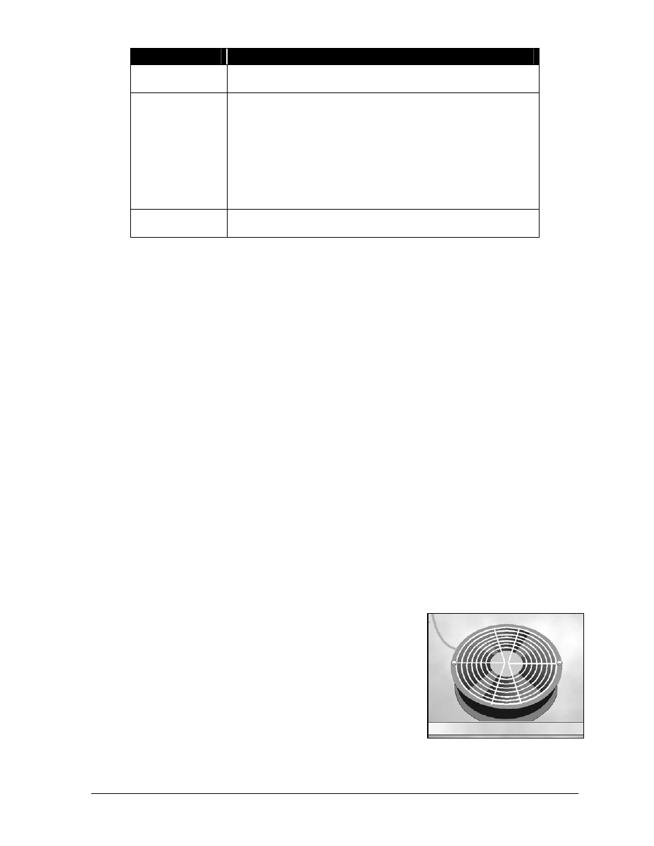
Complete the following steps to remove a fan from the display.
1. Remove the appropriate lens/reflector assembly as
explained in Lens/Reflector Assemblies in Section 4.3.
2. Remove the filter beneath the bad fan as explained in Filters
in Section 4.3.
3. Disconnect the power cord from the fan.
4. On the underside of the cabinet, remove each of the two
nuts holding the fan in place. Refer to Figure 55.
5. Lift the fan from the bottom of the cabinet.
Simply reverse the above steps to install a fan. Remember to connect the power cord.
Component
Function
J1-Data Out
Signal is sent through this connector to the J2 (Input)
connector on the underlying lampbank.
J2-Input On
Venus 1500 systems, signal reaches this connector from
either of the following sources:
•
The master-echo board within the fan control enclosure of
the master display.
•
The J3 (Output) connector of the VSB above it.
On Venus 4600 systems, signal reaches this connector from
either of the following sources:
•
The serial line interface board within that display.
•
The J3 (Output) connector of the VSB above it.
J3-Output
Through this connector, signal is passed to the J2 (Input)
connector of the VSB below.
Figure 55: Typical Fan