Daktronics AB-1600-1.5,2.5 User Manual
Page 37
Electrical Installation
3-15
Lamp brightness levels are set using the Venus software running on the controller computer. Control
brightness by either manually configuring a bright/dim schedule or by letting the optional light
detector adjust lamp brightness as needed.
Following are the optional light detector installation instructions for both Venus 1500 and Venus 4600
systems.
ED9067 and ED4602 contain operation instructions for the Venus 1500 and Venus 4600 software,
respectively. Use the appropriate software manual to configure the display for a light detector if using
one.
Light Detector Installation - Venus 1500 Systems
Instructions for mounting and connecting signal wire to the light detector are located with the light
detector in its box.
A light detector can easily connect to the Venus 1500 display controller as follows.
1. Route the light detector cable (Daktronics part
number W-1234) through conduit and into the
display.
2. Continue the cable into the controller box fitting
labeled “LIGHT.”
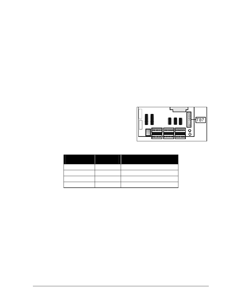
3. Strip the insulation and terminate wires to TB7 as
shown below. TB7 is near the lower-right corner
of the Venus 1500 controller product board, as
seen in Figure 38.
Light
Detector
Field
Cabling
Venus 1500 Controller Term
Block (TB7)
+V
Red
Pin 1 (+5V)
GND
Black
Pin 2 (GND)
P
Green
Pin 3 (Light - P)
N
White
Pin 4 (Light - N)
If a temperature sensor was ordered with this display, refer to Optional Temp Sensor Installation
- Venus 1500 Systems in Section 3.9 for installation instructions.
Proceed to Section 3.10 if all the following statements are true.
•
Signal from the controller computer routes and connects to the Venus 1500 controller within
the display.
•
The light detector connects to the Venus 1500 controller.
•
A temperature sensor was not ordered with this display or is already installed.
•
If this is a 2V, multi-face display, signal interconnects between the displays.
Optional Photo/Temp Sensor Installation - Venus 4600 Systems
Instructions for mounting and connecting signal wire to the light detector are located with the light
detector in its box.
Venus 4600 systems usually have a combination light and temperature sensor. The two devices
integrate into a common circuit board. There is also a photocell-only option available. The only
Figure 38: TB7 on Venus 1500
controller