Daktronics AB-1600-1.5,2.5 User Manual
Page 52
4-10
Maintenance & Troubleshooting
Complete the following steps to remove a lens/reflector assembly from the cabinet.
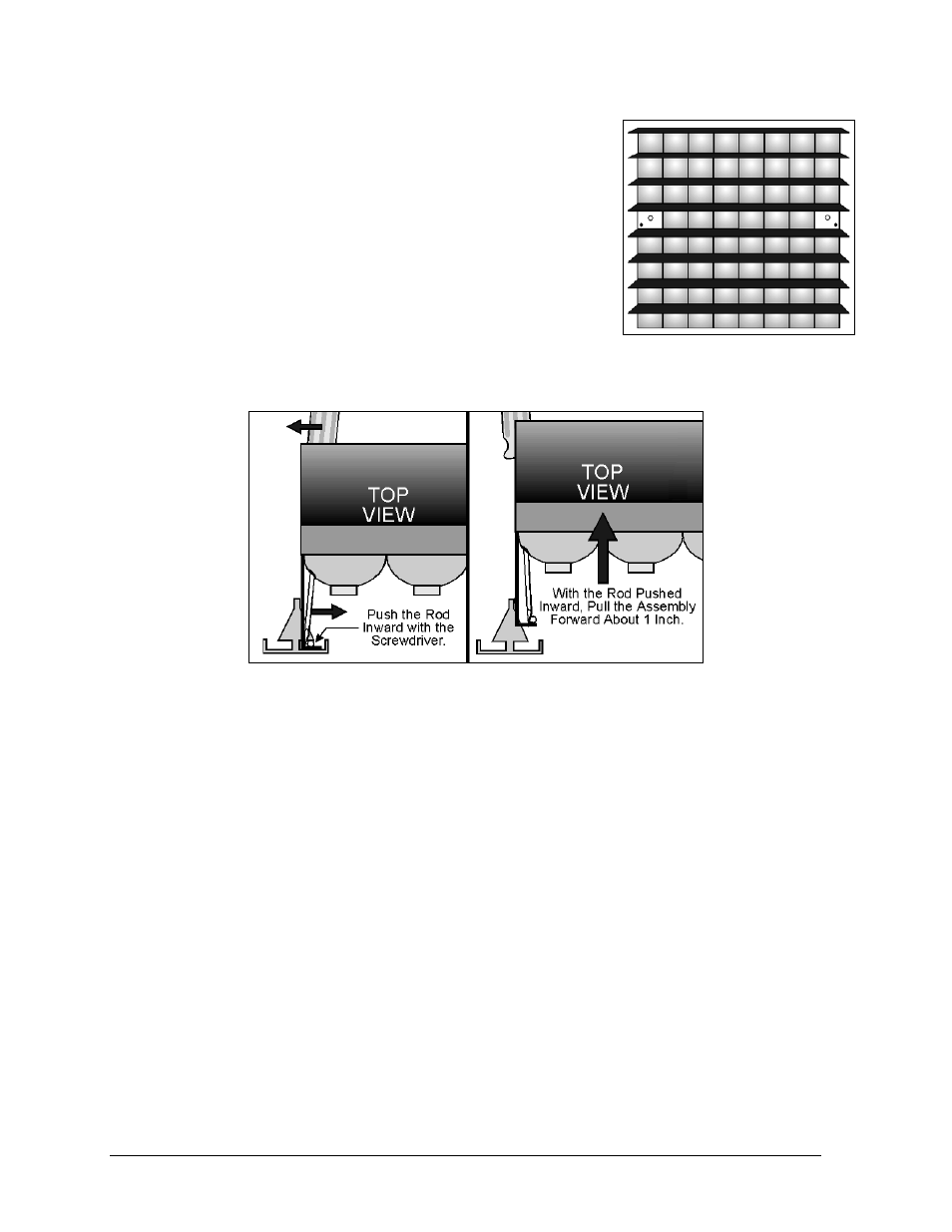
1. Remove the lens from row four, column one, and the lens from
row four, column eight, of the lens/reflector assembly as
illustrated in Figure 50. Lenses in Section 4.3 addresses lens
removal.
2. In the outer corner of each of the two reflector shells is an
access hole. Slide the 10-inch flat head screwdriver into one of
these holes. Keep the screwdriver edge vertical and push it into
the hole, sliding it along the frame until it stops.
3. Use the handle of the screwdriver as a lever to disengage the
latching mechanism on this side of the assembly. Pushing the
screwdriver handle sideways, away from the assembly, will free
this side of the assembly. Figure 51 illustrates this procedure.
Note: It takes only mild pressure on the screwdriver handle
to free each side of the lens/reflector assembly. Excessive
force can bend the rod.
4. While holding the screwdriver handle to the side, pull this side of the assembly out about an
inch. This will pull it free of the latch and prevent it from snapping back into a locked
position.
5. Perform steps 2-4 to free the opposite the opposite side of the assembly.
CAUTION: The lens/reflector assembly is now held in place by only a few ribbon cables.
Do not let the assembly fall from the cabinet.
6. Pull the assembly out of the display far enough to disconnect all ribbon cables and power
connectors from the lampbanks mounted on the assembly’s backside. The assembly is now
completely free of the cabinet.
Complete the following steps to install a lens/reflector assembly in a cabinet.
1. Reconnect all ribbon cables and power connectors to the lampbanks on the back of the
assembly. If this is the left-most assembly in a row (front view), ribbon cables will also need
to be reconnected to the vertical shift board. Refer to Venus 1500 Signal Summary or Venus
4600 Signal Summary in Section 4.2 if unsure which ribbon cables go where.
Figure 50: Assembly with
Lenses
Removed
Figure 51: Assembly Removal