Daktronics AB-1600-1.5,2.5 User Manual
Page 32
3-10
Electrical Installation
TB41-1 (TX-P)
Black
Pin 5 (RX-P)
Pin 6 (N.C)
5. The controller computer connects to the 25-position connector (DB25) within the junction
box. Refer to Drawing A-148870 at the end of this section.
6. Apply silicone sealant around the signal conduit where it meets the display cabinet to prevent
water/moisture from entering the display.
Refer to Light Detector Installation - Venus 1500 Systems in Section 3.8 for instructions on
installing the light detector for this display. If ordering a temperature sensor, refer to Section 3.9
for temp sensor installation instructions.
If this display is one face of a two-face, 2V cabinet display configuration, refer to Section 3.7 for
instructions on running signal from the master to the echo unit.
Venus 1500 System Using RS/422 Signal
RS/422 systems use a six-conductor, unshielded cable to transmit the RS/422 signal from the
signal converter to the display controller. This cable consists of paired wires. It is Daktronics part
number W-1210. Keep the following in mind when working with W-1210 cable.
•
Do not subject W-1210 cable to mechanical flexing after installation.
•
It is not for direct burial.
•
Only route it in a dedicated, grounded metallic conduit.
•
It has a maximum length of 4,000 feet.
Complete the following steps to connect signal to a Venus 1500 system using RS/422 cable.
1. Route conduit and W-1210 cable from the control room to the knockouts on the right side
(rear view) of the display – or master display if installing a 2V configuration.
2. Continue cable into the Venus 1500 controller enclosure fitting labeled “Signal In.”
3. Use the table within this sub-section titled “Venus 1500 RS/422 Signal Connection” to
terminate the W-1210 cable at the Venus 1500 controller and at the signal converter.
•
The connector labeled “RS/422 In” (TB2) is a six-position, Phoenix-style connector found
on the product board of the Venus 1500 controller. Refer to Drawings A-103727 and A-
148859.
•
“J6” is one of two six-position, Phoenix-style connectors found on the side of the signal
converter. Each is clearly labeled.
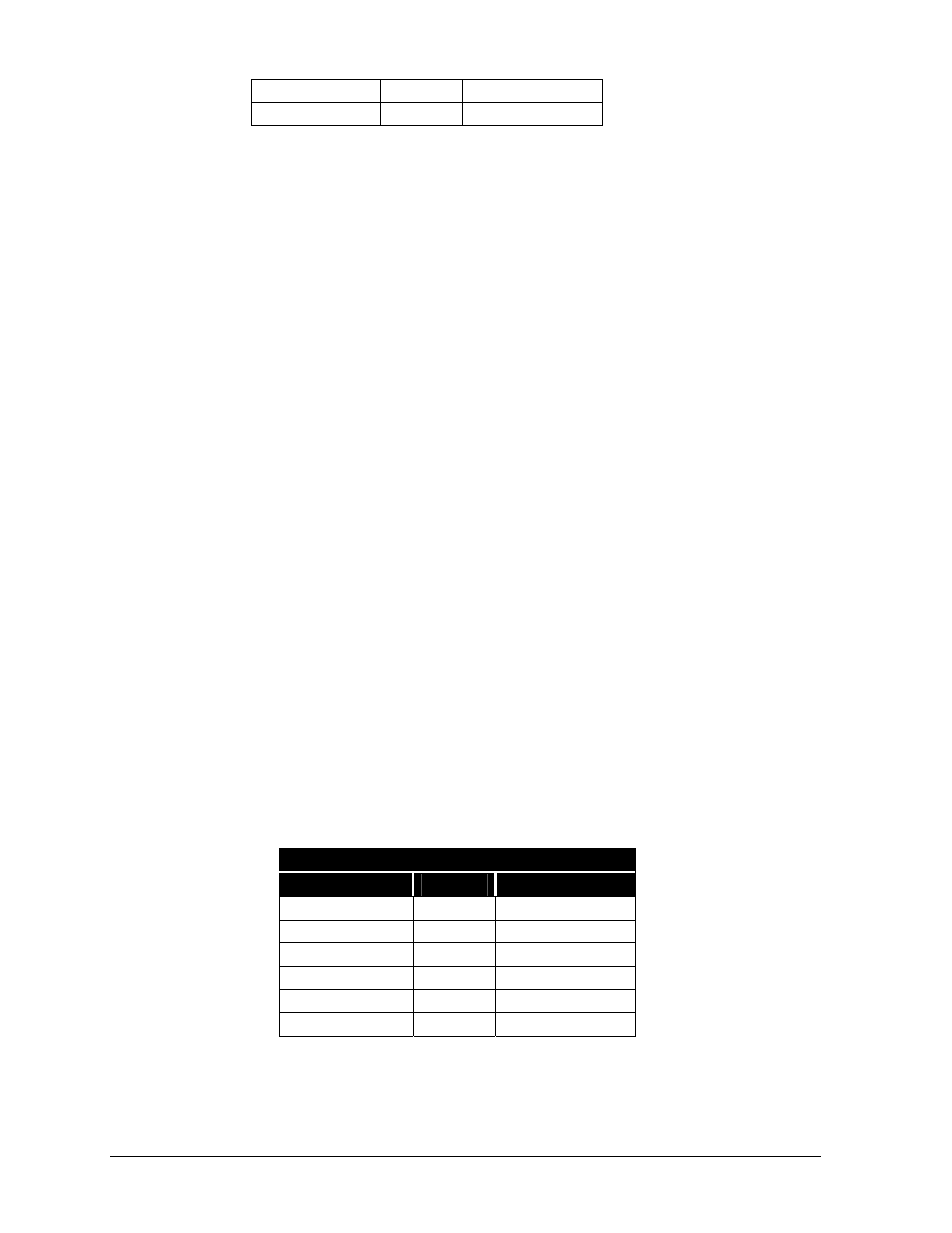
Venus 1500 RS/422 Signal Connection
Sig. Conv. (J6)
Cabling
RS/422 In (TB2)
Pin 1 (GND)
Red
Pin 1 (GND)
Pin 2 (TX-P)
Black
Pin 2 (RX-P)
Pin 3 (TX-N)
Brown
Pin 3 (RX-N)
Pin 4 (RX-P)
White
Pin 4 (TX-P)
Pin 5 (RX-N)
Blue
Pin 5 (TX-N)
Pin 6 (GND)
Green
Pin 6 (GND)
4. The controller computer connects to the 25-position connector (DB25) on the signal converter
labeled “J1.” Refer to Drawing A-148859