Daktronics AB-1600-1.5,2.5 User Manual
Page 61
Maintenance & Troubleshooting
4-19
Additional Venus 4600 System Components (Serial Line Interface)
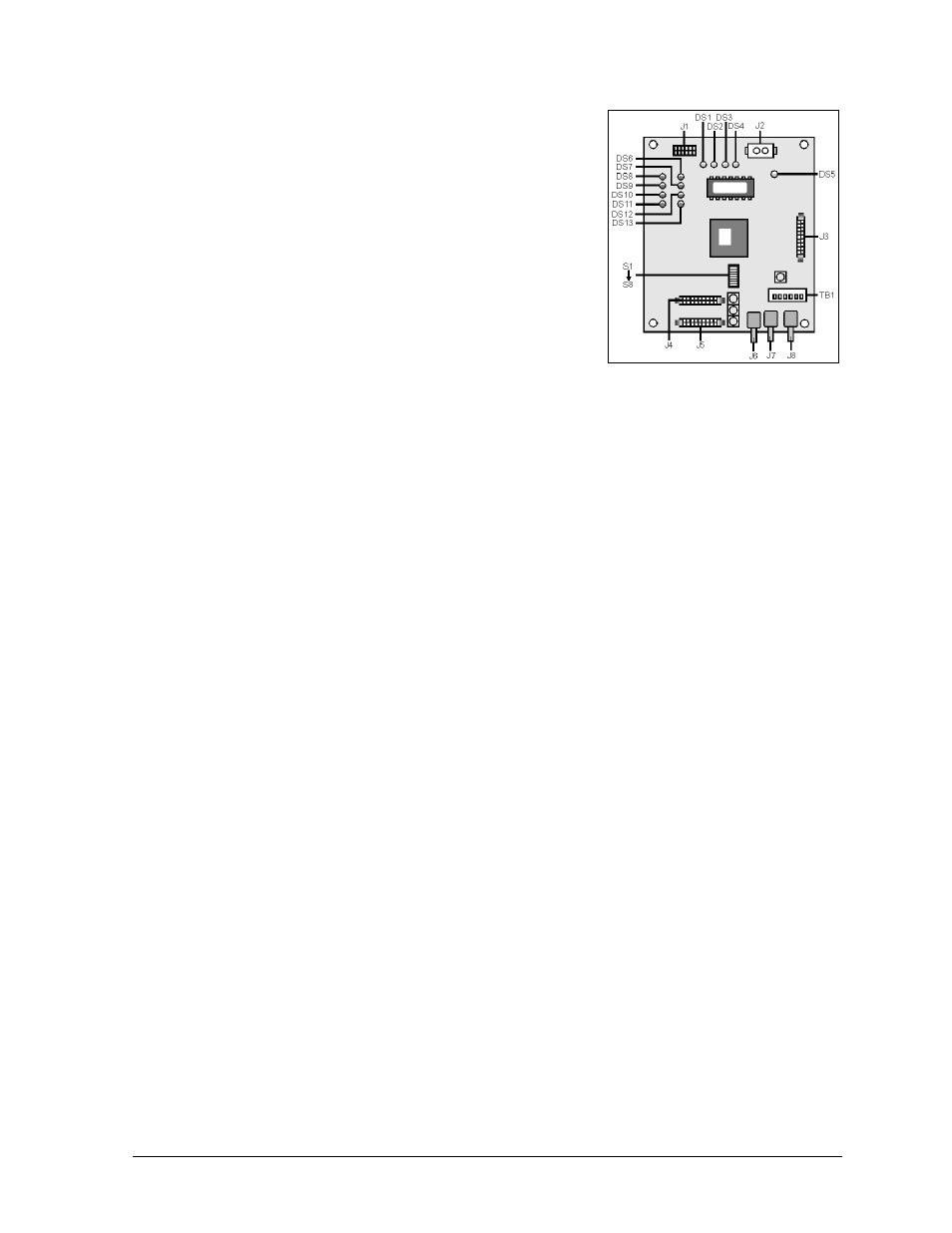
The only component unique to Venus 4600 systems is the
serial line interface board (SLI). The SLI receives data from
the display controller and passes that signal to the vertical
shift boards. The SLI also monitors the status of the display
thermostats. The serial line interface board is illustrated in
Figure 62. It is in the serial line interface enclosure in the
display.
The functions for the diagnostic LEDS found on the serial line
interface board are as follows:
DS1 - Line Fault (red): This indicates if the controller and
data cable connect correctly. With the controller turned on,
and a good fiber optic connection, it should be OFF (it may
flash ON occasionally). If DS1 stays ON there is probably a
break in the fiber optic cable, a bad termination or something
wrong with the controller computer.
DS2 - Test Mode (red): This indicates when the serial line interface is in test mode. If it is ON, a
test pattern will appear on the display.
DS3 - Data (amber): This indicates when the serial line interface is receiving data from the
controller. It will flash ON when receiving data.
DS4 - Bright (red): This indicator will be ON when the photocell is detecting a full bright light
level and OFF for other light levels. If no photocell is connected to the serial line interface, it will
flash.
DS5 - Power (green): This indicates when the power on the serial line interface is working. It
should ALWAYS be ON.
DS6 - DS13 - Thermostat Inputs (all red): These indicate proper cooling of the display. These
should ALL be ON. An OFF LED indicates a thermostat has opened due to excessive heat buildup
within the display cabinet, possibly due to a failed fan or a dirty filter. When this occurs, the serial
line interface will automatically blank the display to prevent heat damage to the electrical
components.
DS6 corresponds to thermostat 1 in the cabinet and DS13 corresponds to thermostat 8 in the cabinet.
The thermostats are numbers from left to right when the display is viewed from the front. The
thermostats are located on the mounting bolts for the transformer. For 16
́́
or 24
́́́́́́
high displays, the
thermostats are on the upper most transformer only. Refer to appropriate shop drawing.
When the internal cabinet temperature drops to acceptable levels, the thermostats will close. The
serial line interface will sense this and restore the display to normal operation.
DS14 - Program (red): This indicates the serial line interface powered-up OK. It should be ON.
DS15 and/or DS16 -Transmit (both red): Indicate(s) signal transmission out of the fiber optic
transmitter(s) (to the echo face).
Figure 62: Serial Line Interface
Detail