Daktronics AB-1600-1.5,2.5 User Manual
Page 47
Maintenance & Troubleshooting
4-5
jack on the serial line interface board. If a echo display is present, the data is shared with the
displays by running a fiber optic cable between J6 or J7 (TX) on the master display’s serial
line interface to J8 (RX) on the echo display’s serial line interface.
From the serial line interface board, display information routes to the vertical shift board
behind the upper-left-most lampbank (front view). A 20-pin ribbon cable connects J4 on the
serial line interface to J2 (Input) on the vertical shift board.
The vertical shift board then sends the display information to the lampbank on which it is
mounted. A 20-pin ribbon cable connects J1 (Data Out) on the vertical shift board to J2
(Input) on the lampbank. On 16 and 24-high displays, J3 (Output) on each vertical shift board
connects to J2 (Input) on the vertical shift board below it. Each display row has one vertical
shift board behind the left-most lampbank (front view).
The display data then cascades down the row as it passes from J3 (Output) on each lampbank
to J2 (Input) on the next lampbank over 20-pin ribbon cable.
The button thermostats in this display connect to a junction panel within the fan controller
enclosure. A wire harness runs from this panel to J1 (Fans) on the serial line interface board.
The thermostats in the echo display, if there is one, run to that display’s junction panel and
then to that display’s serial line interface.
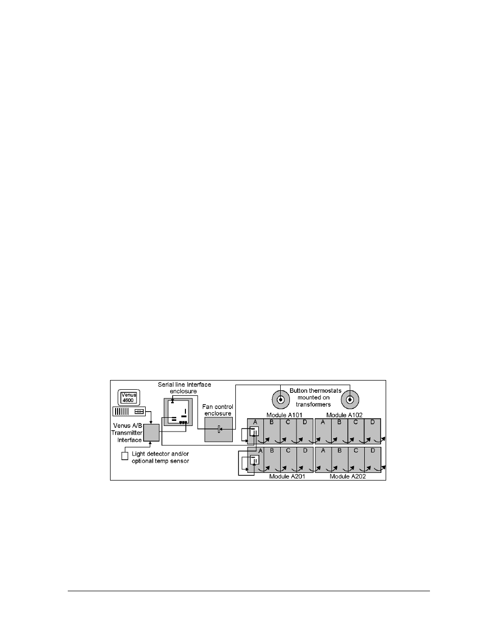
The photocell, if ordered with the display, connects to the Venus A/B transmitter interface at
TB1 inside the transmitter case.
Figure 44 illustrates the signal routing for a Venus 4600, 16-high display. The illustration is
for conceptual purposes only. The display cabinet houses all components except the controller
computer, light detector (photocell) and the Venus A/B transmitter interface.
For detailed power and signal information, refer to the appropriate general schematic at the
end of this section or the project specific schematic in Appendix A, if one was included.
Refer to Section 4.2 if unsure which schematic to use.
Ventilation & Temperature Sensing Summary
Daktronics 1600 series small matrix displays depend on a ventilation system and internal
temperature sensing equipment to prevent and monitor heat buildup within the cabinet. Excessive
heat shortens the life of all electrical components, including lamps.
Figure 44: Signal Routing for Venus 4600, 16-High Display