Daktronics AB-1600-1.5,2.5 User Manual
Page 59
Maintenance & Troubleshooting
4-17
Complete the following steps to remove the Venus 1500 controller.
1. Flip the main disconnect to the OFF position.
2. Disconnect all power and signal connections from the controller board.
3. Remove the nuts holding the controller board in the enclosure.
4. Write down the MDC switch settings.
5. If this display uses fiber optic or modem communication, remove the fiber optic or
modem board from the controller board by removing the nuts.
6. If sending the controller (controller board and MDC board) back to Daktronics, keep the
modem or fiber board (if present) and all mounting hardware.
When installing a new display controller, verify the MDC DIP switch is set correctly.
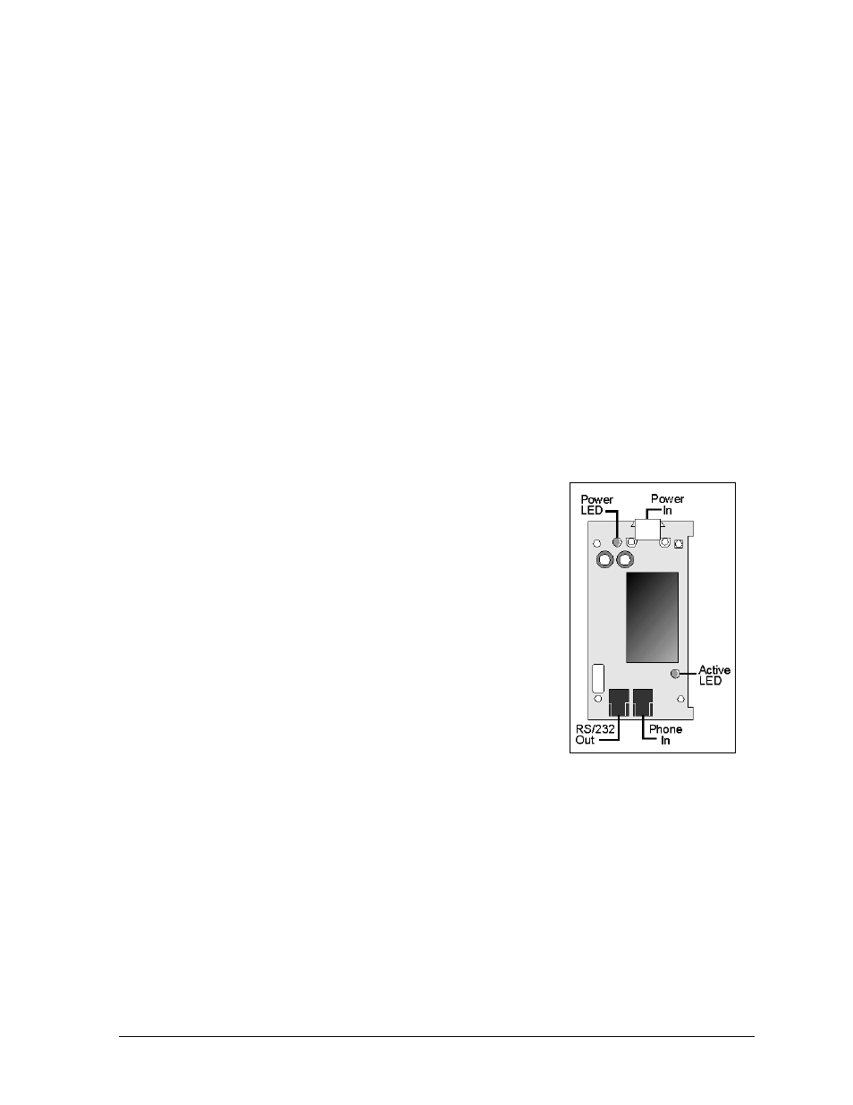
Optional Modem Board
The modem board has two LED’s. A lit Power LED indicates the modem board is receiving
power. The Active LED will light when the modem initialized and when it is in the process of
communicating. The modem phone input connects to the telephone terminal block with a
small, straight RJ11 cable. The modem RS/232 Out connects to the controller board J1 RS232
In with a small, straight RJ11 cable.
A modem system requires jumpers to be set on the modem board. Refer to Controller Board
and MDC Board in Section 4.3 for jumper settings.
Complete the following steps to replace a modem:
1. Turn off display power at power disconnect.
2. Disconnect the power and signal connections. Figure 59
illustrates the modem board connectors.
3. Remove the four nuts on top of the modem board.
4. Insert the new modem, replace the screws, reconnect the
power, and signal connections.
Optional Fiber Optic Board
The fiber optic board has LEDs. A lit Power LED indicates
the modem board is receiving power. The Receive LED
(DS2) will light when the fiber optic board is accepting
signal from the controller computer. The Transmit LED
(DS3) will light when the display fiber optic board is sending
signal to the computer fiber optic board. In addition, the fiber
module has two incoming fiber connectors and two outgoing
fiber connectors. The fiber optic board connects to the controller board with a small flipped
PC connector cable (DB9F to RJ11 - RS/232 Out).
Figure 59: Optional
Modem Board